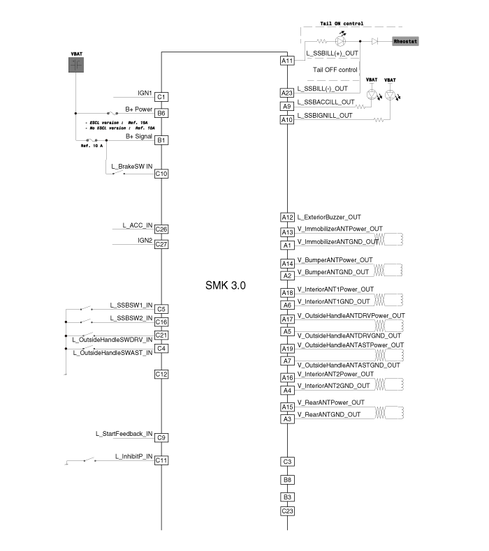
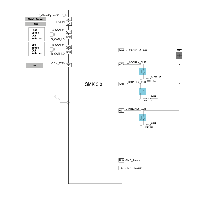
 Kia Sedona: Smart key unit Schematic Diagrams
Third generation YP (2014-2025) / Kia Sedona YP Service Manual / Body Electrical System / Smart key System / Smart key unit Schematic Diagrams
| Schematic Diagrams |


 Smart key unit Components and Components Location
Components (1)
Connector Pin Information
No.Connector AConnector BConnector C1Immobilizer antenna GND outputB+IGN12Bumper antenna GND output--3Rear antenna GND output--4Interior antenna 2 GND ou ...
 Smart key unit Repair procedures
Removal
Smart Key Unit
1.
Disconnect the negative (-) battery terminal.
2.
Remove the crash pad lower panel.
(Refer to Body - "Crash Pad Lower Panel")
3.
Remove the glove box housing.
( ...
Other Information:
Schematic Diagrams
SVM System Input/Output
1.
Camera input
ItemSpecificationLens angle of view190 degreesAngle of viewHorizontal186 degreesVertical135 degreesFunctionProvides the original image of the wide ang ...
Press brake pedal to start engine (for smart key system)
This warning message illuminates if the Engine Start/Stop Button changes
to the ACC position twice by pressing the button repeatedly without depressing
the brake pedal.
It means that you ...
Categories
- Home
- First Generation
- Second Generation
- Third generation
- Kia Sedona YP 2014-2025 Owners Manual
- Kia Sedona YP 2014-2025 Service Manual
Copyright В© www.kisedona.com 2016-2025
