 Kia Sedona: Smart key unit Components and Components Location
Third generation YP (2014-2026) / Kia Sedona YP Service Manual / Body Electrical System / Smart key System / Smart key unit Components and Components Location
| Components (1) |
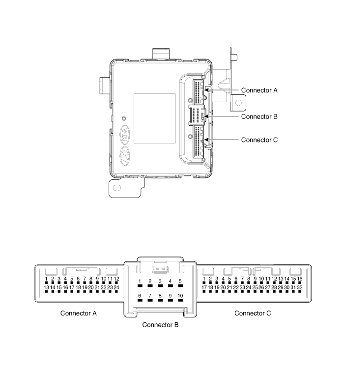
Connector Pin Information
| No. | Connector A | Connector B | Connector C |
| 1 | Immobilizer antenna GND output | B+ | IGN1 |
| 2 | Bumper antenna GND output | - | - |
| 3 | Rear antenna GND output | - | - |
| 4 | Interior antenna 2 GND output | - | Passenger''s door switch |
| 5 | Driver''s door antenna GND output | GND power2 | SSB_switch1 inpuf |
| 6 | Interior antenna 1 GND output | B+POWER | COM EMS |
| 7 | Passenger''s door antenna GND output | - | RPM signal inpuf |
| 8 | SSB Illumination (OFF) output | - | Wheel speed input |
| 9 | SSB Illumination (ACC) output | - | Start Feedback signal inpuf |
| 10 | SSB Illumination (IGN) output | GND power1 | Brake switch signal input |
| | |||
| 11 | SSB Illumination (+) output | | P signal input (AT specification) |
| 12 | Exterior buzzer output | - | |
| 13 | Immobilizer antenna power output | - | |
| 14 | Bumper antenna power output | - | |
| 15 | Rear antenna power output | - | |
| 16 | Interior antenna 2 power output | SSB switch2 inpuf | |
| 17 | Driver''s door antenna power output | C CAN HIGH | |
| 18 | Interior antenna 1 power output | C CAN LOW | |
| 19 | Passenger''s door antenna power output | B CAN LOW | |
| 20 | IGN1 relay output | B CAN HIGH | |
| 21 | IGN2 relay output | Driver''s door switch input | |
| 22 | ACC relay output | - | |
| 23 | SSB Illumination (-) output | - | |
| 24 | Starter relay output | - | |
| 25 | | - | |
| 26 | ACC inpuf | ||
| 27 | IGN2 | ||
| 28 | - | ||
| 29 | - | ||
| 30 | - | ||
| 31 | - | ||
| 32 | - |
 Smart key Repair procedures
Smart Key
Smart Key Code Saving
1.
Connect the DLC cable of GDS to the data link connector (16
pins) in driver side crash pad lower panel, and then turn the power on
GDS.
2.
Select the ve ...
 Smart key unit Schematic Diagrams
Schematic Diagrams
...
Other Information:
To convert to cruise control mode
The driver may choose to only use the cruise control mode (speed control function)
by doing as follows:
1.Turn the SCC on (the cruise indicator light will be on but the system will
not be act ...
Timing Chain Cover Components and Components Location
Components
1. Timing chain cover2. Gasket
...
Categories
- Home
- First Generation
- Second Generation
- Third generation
- Kia Sedona YP 2014-2026 Owners Manual
- Kia Sedona YP 2014-2026 Service Manual

Copyright © www.kisedona.com 2016-2026