 Kia Sedona: Smart key unit Schematic Diagrams
Third generation YP (2014-2026) / Kia Sedona YP Service Manual / Body Electrical System / Smart key System / Smart key unit Schematic Diagrams
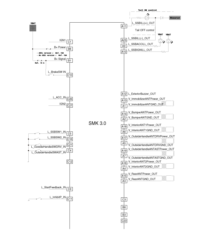
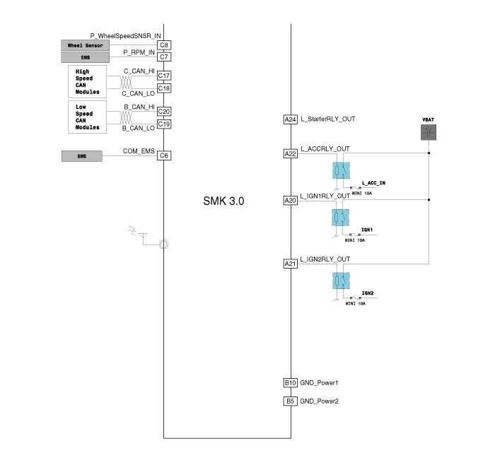
| Schematic Diagrams |
 Smart key unit Components and Components Location
Components (1)
Connector Pin Information
No.Connector AConnector BConnector C1Immobilizer antenna GND outputB+IGN12Bumper antenna GND output--3Rear antenna GND output--4Interior antenna 2 GND ou ...
 Smart key unit Repair procedures
Removal
Smart Key Unit
1.
Disconnect the negative (-) battery terminal.
2.
Remove the crash pad lower panel.
(Refer to Body - "Crash Pad Lower Panel")
3.
Remove the glove box housing.
( ...
Other Information:
Power Steering Hoses Components and Components Location
Components Location
1. Cooler tube2. Pressure hose3. Suction hose4. Return tube & hose
...
Blind Spot Detection Switch Repair procedures
Removal
1.
Disconnect the negative (-) battery terminal.
2.
Remove the crash pad lower panel.
(Refer to Body - "Crash Pad Lower Panel")
3.
Remove the crash pad lower switch (A) after loos ...
Categories
- Home
- First Generation
- Second Generation
- Third generation
- Kia Sedona YP 2014-2026 Owners Manual
- Kia Sedona YP 2014-2026 Service Manual

Copyright © www.kisedona.com 2016-2026