 Kia Sedona: Instrument Cluster Schematic Diagrams
Third generation YP (2014-2026) / Kia Sedona YP Service Manual / Body Electrical System / Indicators And Gauges / Instrument Cluster Schematic Diagrams
| Circuit Diagram |
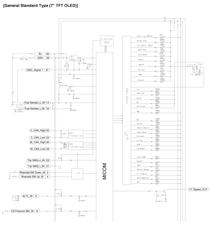
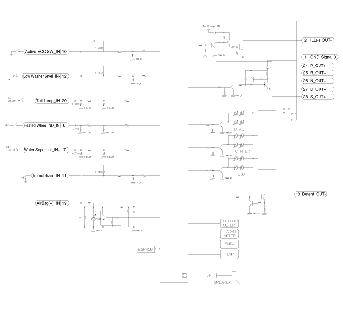
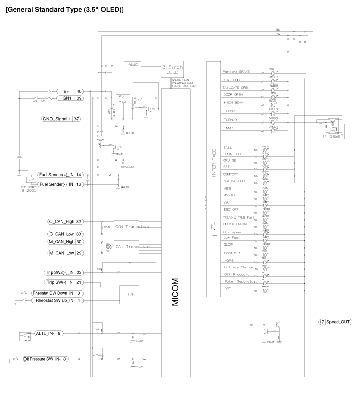
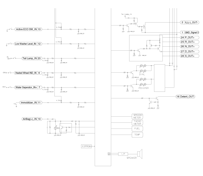
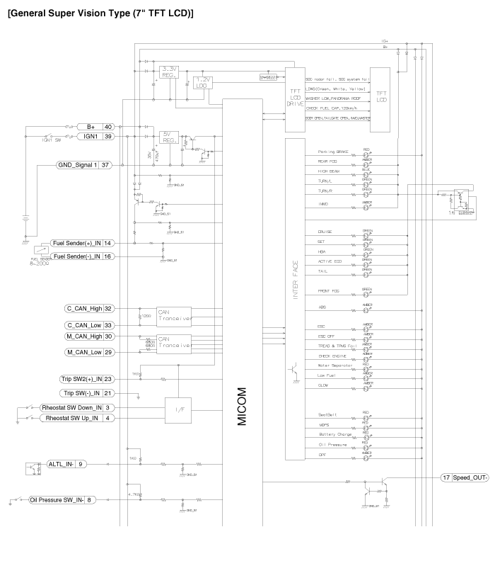
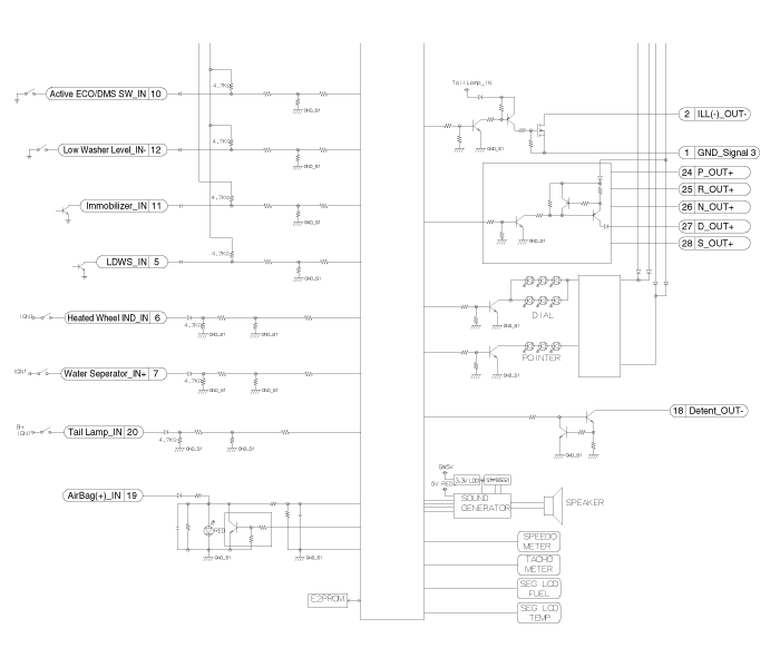
 Instrument Cluster Components and Components Location
Components
Connector Pin Information
No.DescriptionNo.Description1Ground signal321Trip switch1_Input (-) 2Illumination output (-)22-3Rheostat switch (Down)_Input23Trip switch2_Input (-)&nbs ...
 Instrument Cluster Description and Operation
Description
Communication Network Diagram
AbbreviationExplanationACUAirbag Control UnitADMAssist Door ModuleB_CANBody Controller Area NetworkBCMBody Control ModuleBSDBlind Spot DetectionC_CANCha ...
Other Information:
Seatback angle
2nd row seat
2nd row center seat
2nd row seat for SXL package
3rd row seat
To recline the seatback :
1. Pull up the seatback recline lever (for 2nd row outboard seat) or strap (for
2nd ...
Master Cylinder Repair procedures
Removal
1.
Turn ignition switch OFF and disconnect the negative (-) battery cable.
2.
Remove the air cleaner assembly (A).
3.
Disconnect the brake fluid level switch connector (B), and rem ...
Categories
- Home
- First Generation
- Second Generation
- Third generation
- Kia Sedona YP 2014-2026 Owners Manual
- Kia Sedona YP 2014-2026 Service Manual
Copyright © www.kisedona.com 2016-2026
