 Kia Sedona: Instrument Cluster Components and Components Location
Third generation YP (2014-2026) / Kia Sedona YP Service Manual / Body Electrical System / Indicators And Gauges / Instrument Cluster Components and Components Location
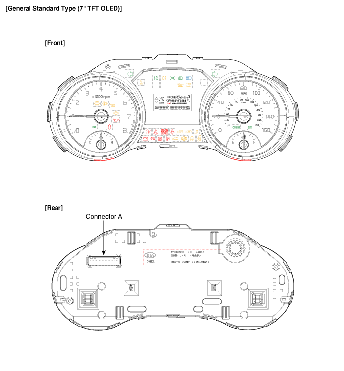
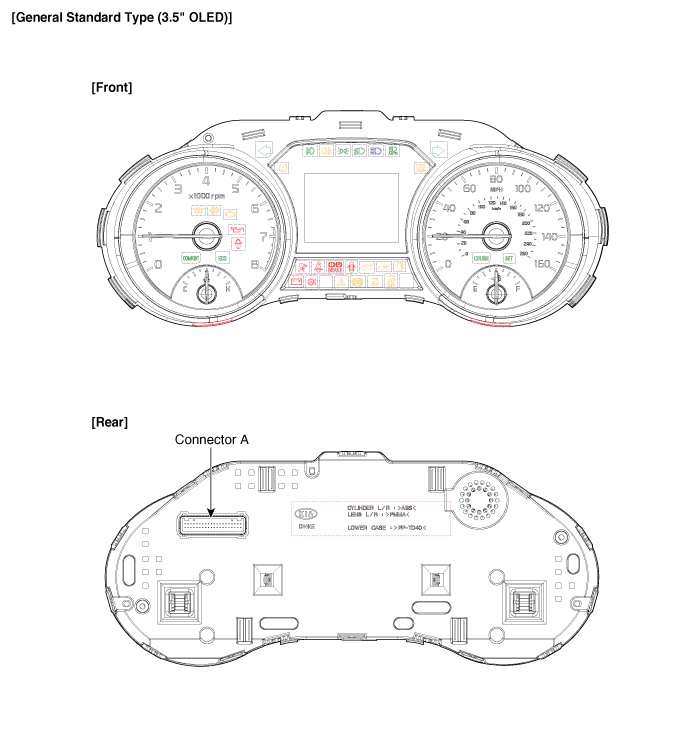
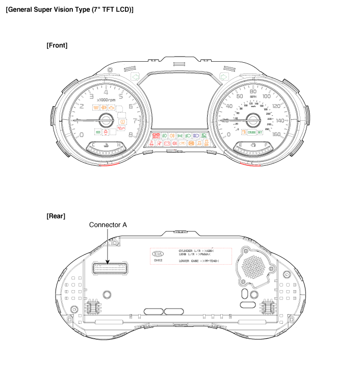
| Components |
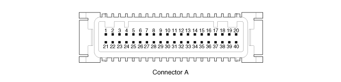
Connector Pin Information
| No. | Description | No. | Description |
| 1 | Ground signal3 | 21 | Trip switch1_Input (-) |
| 2 | Illumination output (-) | 22 | - |
| 3 | Rheostat switch (Down)_Input | 23 | Trip switch2_Input (-) |
| 4 | Rheostat switch (Up)_Input | 24 | AT (''P'' Position) (+) |
| 5 | LDWS_Input | 25 | AT (''R'' Position) (+) |
| 6 | Steering wheel heated indicator_Input | 26 | AT (''N'' Position) (+) |
| 7 | Water seperator_Input (+) | 27 | AT (''D'' Position) (+) |
| 8 | Oil pressure switch_Input (-) | 28 | AT (''S'' Position) (+) |
| 9 | ALTL Input (-) | 29 | Multimedia-CAN (Low) |
| 10 | Active ECO/DMS switch_Input | 30 | Multimedia-CAN (High) |
| 11 | Immobilizer_Input | 31 | - |
| 12 | Low washer level_Input (-) | 32 | Chassis-CAN (High) |
| 13 | - | 33 | Chassis-CAN (Low) |
| 14 | Fuel sender_Input (+) | 34 | - |
| 15 | - | 35 | - |
| 16 | Fuel sender_Input (-) | 36 | - |
| 17 | Speed_Output (-) | 37 | Ground signal1 |
| 18 | Detent_Output (-) | 38 | - |
| 19 | Airbag_Input (+) | 39 | IGN1 |
| 20 | Tail lamp_Input | 40 | Battery (+) |

 Instrument Cluster Schematic Diagrams
Circuit Diagram
...
Other Information:
Aux, USB port
If your vehicle has an aux and/or USB(universal serial bus) port, you can use
an aux port to connect audio devices and an USB and also an iPod ...
Finish maintenance
Washing
To help protect your vehicle ...
Categories
- Home
- First Generation
- Second Generation
- Third generation
- Kia Sedona YP 2014-2026 Owners Manual
- Kia Sedona YP 2014-2026 Service Manual

Copyright © www.kisedona.com 2016-2026