 Kia Sedona: Power Sliding Door (PSD) Switch Repair procedures
Third generation YP (2014-2026) / Kia Sedona YP Service Manual / Body Electrical System / Power Sliding Door System / Power Sliding Door (PSD) Switch Repair procedures
| Inspection |
Overhead Console Door Switch Inspection
| 1. |
When inspecting, use the inspection equipment to check for
input/output values of Overhead console door switch. If there''s any
malfunctioning, check the IPM and replace. |
| 2. |
To check the operation of Overhead console door switch, choose "IPM" menu and vehicle. |
| 3. |
Select the sensor output after choosing IPM. |
| 4. |
Check for PSD PTG power supply control switch and output value of PSD switch (left/right) |
| 5. |
Operate the Overhead console switch in on and off mode and check if the output value is changed. |
Door Handle Switch Inspection
| 1. |
When inspecting, use the inspection equipment to check for
input/output values at each position of Power Sliding Door control
module. If there''s any malfunctioning, replace the Power Sliding Door
control module. |
| 2. |
To check the operation of Handle switch, choose “Power Sliding/Tailgate” menu and vehicle. |
| 3. |
Select "Power Sliding Door" that needs inspection. |
| 4. |
After selecting sensor output, use the handle switch and check the output value of handle switch by operating PSD or PTG. |
| 5. |
Check that output value of handle switch changes properly from OFF to ON during operation. |
Trim Switch Inspection
| 1. |
When inspecting, use the inspection equipment to check the input/output values of the trim switch. |
| 2. |
To check the operation of the trim switch, choose “IPM” menu and vehicle. |
| 3. |
Select RAM and select the sensor output value. |
| 4. |
Check the output value of PSD/LSD left/right door switch. |
| 5. |
Operate the Center Pillar trim door switch in on and off modes and check that the output value changes. |
| Removal |
Over Head Console Switch
| 1. |
Disconnect the negative (-) battery terminal. |
| 2. |
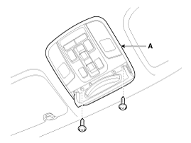
Remove the over head console lamp switch (A) after loosening the screws.
|
| 3. |
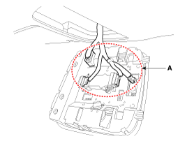
Disconnect the connector (A) from over head console lamp switch.
|
Center Pillar Trim Switch
| 1. |
Disconnect the negative (-) battery terminal. |
| 2. |
Remove the center pillar lower trim.
(Refer to Body - "Center Pillar Trim") |
| 3. |
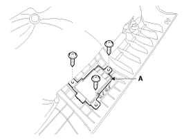
Remove the power sliding door switch (A) after loosening the screws.
|
| Installation |
Over Head Console Switch
| 1. |
Connect the over head console lamp connector. |
| 2. |
Install the over head console lamp. |
| 3. |
Connect the negative (-) battery terminal. |
Center Pillar Trim Switch
| 1. |
Install the power sliding door switch. |
| 2. |
Install the center pillar lower trim. |
| 3. |
Connect the negative (-) battery terminal. |
 Latch Switch Repair procedures
Inspection
1.
When inspecting, use the inspection equipment to check for
input/output values at each position of Power Sliding Door control
module.
2.
To check the operation of latch, cho ...
 Anti-Pinch Strip Repair procedures
Inspection
1.
Use the GDS to check input/output values in the Power Sliding
Door control module for each position. If there''s any malfunctioning,
replace the anti-pinch strip.
2.
To chec ...
Other Information:
Troubleshooting
Troubleshooting
Limp Home Mode
Features a fail-safe function that prevents dangerous
situations in the event of a transaxle failure.The vehicle will be
driven in limp home mode if the transa ...
Multimedia Jack Schematic Diagrams
Circuit Diagram
...
Categories
- Home
- First Generation
- Second Generation
- Third generation
- Kia Sedona YP 2014-2026 Owners Manual
- Kia Sedona YP 2014-2026 Service Manual
Copyright © www.kisedona.com 2016-2026


