
 Kia Sedona: Output Speed Sensor Schematic Diagrams
Third generation YP (2014-2026) / Kia Sedona YP Service Manual / Automatic Transaxle System / Automatic Transaxle Control System / Output Speed Sensor Schematic Diagrams
| Circuit Diagram |
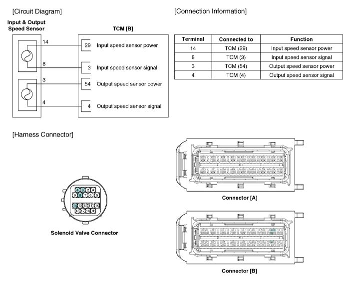
 Output Speed Sensor Description and Operation
Description
•
Output speed sensor uses an electric current type hall sensor in which the current is changed by the magnetic variation.
•
Output speed sensor (A) and input speed ...
 Output Speed Sensor Repair procedures
Inspection
1.
Turn ignition switch OFF.
2.
Remove the battery and battery tray.
(Refer to Engine Electrical System - "Battery")
3.
Disconnect the solenoid valve connector (A).
4.
M ...
Other Information:
Cylinder Head Components and Components Location
Components
1. RH Cylinder head2. RH Cylinder head gasket3. LH Cylinder head4. LH Cylinder head gasket5. Cylinder block
1. Camshaft bearing cap 2. Camshaft thrust bearing cap 3. RH Exhaust ca ...
Bright-metal maintenance
To remove road tar and insects, use a tar remover, not a scraper or other
sharp object.
To protect the surfaces of brightmetal parts from corrosion, apply a coating
of wax or chrome preserv ...
Categories
- Home
- First Generation
- Second Generation
- Third generation
- Kia Sedona YP 2014-2026 Owners Manual
- Kia Sedona YP 2014-2026 Service Manual

Copyright © www.kisedona.com 2016-2026