 Kia Sedona: Rear Sub Frame Repair procedures
Third generation YP (2014-2025) / Kia Sedona YP Service Manual / Suspension System / Rear Suspension System / Rear Sub Frame Repair procedures
| Removal |
| 1. |
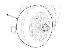
Remove the rear wheel and tire (A) from rear hub.
|
| 2. |
Remove the rear caliper assembly.
(Refer to Brake System - "Rear Disc Brake") |
| 3. |
Remove the parking barke cable.
(Refer to Brake System - "Parking Brake Assembly") |
| 4. |
Remove the rear muffler.
(Refer to Engine Mecanical System - "Muffler") |
| 5. |
Remove the rear shock absorber bar.
(Refer to Suspension System - "Rear Shock Absorber") |
| 6. |
Remove the rear assist arm.
(Refer to Suspension System - "Rear Assist Arm") |
| 7. |
Remove the rear upper arm.
(Refer to Suspension System - "Rear Upper Arm") |
| 8. |
Remove the rear lower arm.
(Refer to Suspension System - "Rear Lower Arm") |
| 9. |
Remove the trailing arm.
(Refer to Suspension System - "Trailing Arm") |
| 10. |
Remove the rear stabilizer bar.
(Refer to Suspension System - "Rear Stabilizer Bar") |
| 11. |
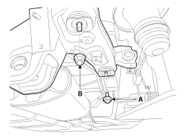
Remove the rear sub frame.
|
| 12. |
Install in the reverse order of removal. |
| 13. |
Check the rear alignment.
(Refer to Rear Suspension System - "Rear Alignment") |
 Rear Stabilizer Bar Repair procedures
Removal
1.
Remove the rear wheel and tire (A) from rear hub .
Tightening torque:
88.2 ~ 107.8 N.m (9.0 ~ 11.0 kgf.m, 65.0 ~ 79.5 lb-ft)
Be careful not to damage ...
 Rear Alignment Repair procedures
Rear wheel alignment
When using a commercially available computerized wheel
alignment equipment to inspect the rear wheel alignment, always position
the vehicle on ...
Other Information:
General Information
Lift And Support Points
When heavy rear components such as suspension, fuel tank,
spare tire, tailgate and trunk lid are to be removed, place additional
weight in t ...
Smart cruise control system (SCC)
➀ Cruise indicator
➁ SET indicator
➂ Set speed
➃ Vehicle-to-vehicle distance
The SCC allows you to program the vehicle to maintain a set speed so long as
it is no ...
Categories
- Home
- First Generation
- Second Generation
- Third generation
- Kia Sedona YP 2014-2025 Owners Manual
- Kia Sedona YP 2014-2025 Service Manual
Copyright В© www.kisedona.com 2016-2025


