 Kia Sedona: Smart Cruise Control Unit Repair procedures
Third generation YP (2014-2026) / Kia Sedona YP Service Manual / Engine Electrical System / Smart Cruise Control System / Smart Cruise Control Unit Repair procedures
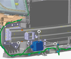
| Removal |
| 1. |
Remove the bumper.
(Refer to Body - "Front Bumper") |
| 2. |
Disconnect the smart cruise control unit connector. |
| 3. |
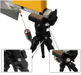
Remove the smart cruise control unit assembly (A) from vehicle after loosening mounting bolts (B).
|
| Installation |
| 1. |
Install in the reverse order of removal. |
| 2. |
Align the smart cruise control sensor.
(Refer to Engine Electrical System - "Smart Cruise Control(SCC) Alignment") |
| 3. |
Install the bumper cover.
(Refer to Body - "Front Bumper Cover") |
| Smart Cruise Control (SCC) Sensor Alignment |
Smart Cruise Control (SCC) unit detects a forward vehicle and
then recognizes the distance to the forward vehicle and the relative
speed using the built-in radar sensor. In order for the radar sensor to
operate correctly, it must be properly aligned parallel to the driving
direction of the vehicle. So, the radar sensor alignment procedure must
be carried out after the sensor is reinstalled or replaced with new one.
If not performing the sensor alignment in the conditions mentioned
above, the smart cruise control system may not operate correctly.
The SCC radar sensor alignment is required when:
|

The sensor can not recognize a vehicle ahead:
|

Smart Cruise Control (SCC) Radar Alignment
| 1. |
Stop the vehicle on a level ground.
|
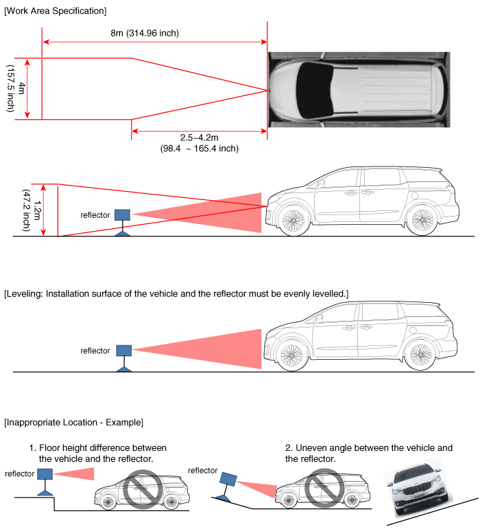
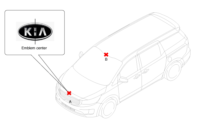
| 2. |
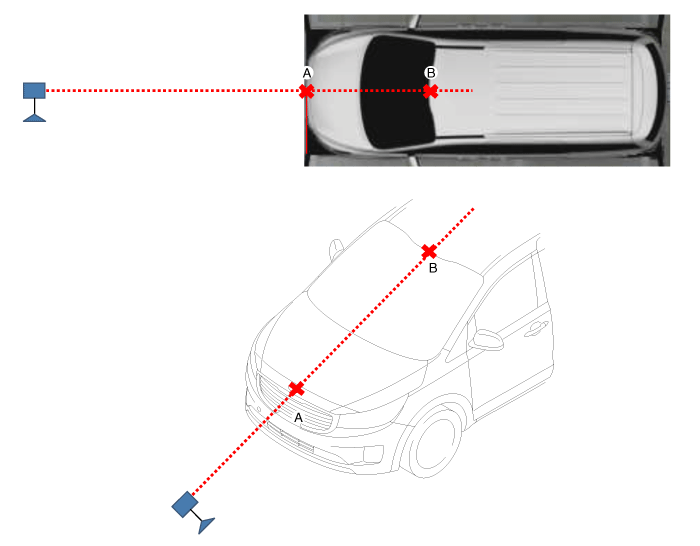
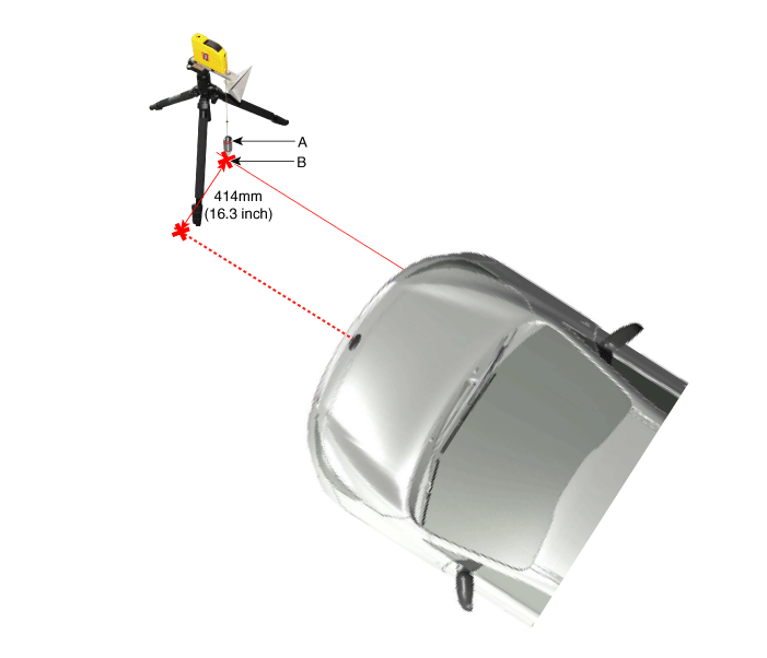
Mark the center point of emblem (A) and the center point on top of wind glass (B).
|
| 3. |
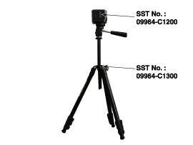
Connect the SCC Calibration Laser (SST No. : 09964-C1200) to the tripod (SST No. : 09964-C1300).
|
| 4. |
Match the vertical line of laser to (A) and (B) using the SCC calibration laser pointer.
|
| 5. |
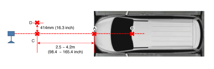
Mark (C) located in 2.5~4.2 m (98.4 ~ 165.4 inch) from (A) in front of the vehicle. |
| 6. |
Mark (D) at the place which is 414 mm (16.3 inch) away from (C) to the left in vertical direction.
|
| 7. |
Disconnect the SCC Calibration Laser (SST No. : 09964-C1200) from the tripod (SST No. : 09964-C1300). |
| 8. |
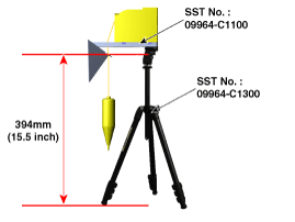
Connect the reflector (SST No. : 09964-C1100) to the tripod
(SST No. : 09964-C1300) and set the reflector center height to 394 mm.
|
| 9. |
Set the reflector horizontal using the leveler which is built in the tripod (SST No. : 09964-C1300).
|
| 10. |
Install the reflector to match the weight (A) with the point (B).
|
| 11. |
Check again the radar sensor and the surface of front bumper for the following items with the eyes.
|
| 12. |
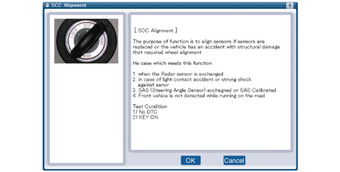
Connect the GDS to the DLC of the vehicle and start sensor alignment.
|
| 13. |
After correctly selecting the vehicle model, select "SCC Alignment" from the auxiliary functions in GDS Menu.
|
| 14. |
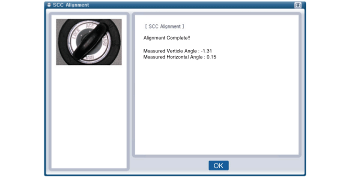
Perform sensor alignment by following the directions shown on the GDS monitor.
|
| 15. |
In case of sensor alignment failure, check the alignment
conditions. Turn the ignition key OFF, then reperform the sensor
alignment procedure. |
| Inspection |
Inspection procedures for smart cruise control system failure:
| 1. |
Check the bumper appearance and accident history (visual appearance of the vehicle, maintenance and bumper replacement history).
→ If the vehicle has been crashed, SCC mounting part is highly likely to be twisted. |
| 2. |
Check whether the radar sensor cover of the bumper is dirty.
→ If the cover is dirty, SCC is highly likely to be released by the foreign substance during operation. |
| 3. |
After starting engine, check SCC warning message on the cluster and DTC code. (Refer to DTC guide.) |
| 4. |
After starting engine, stop for more than 5 seconds.
→ If system initialization (yaw rate sensor offset compensation) is not completed, SCC will not operate. |
 Smart Cruise Control Unit Schematic Diagrams
Circuit Diagram
...
 Smart Cruise Control Switch Components and Components Location
Components
1. Remote control switch (LH) 2. Remote control switch (RH)
...
Other Information:
Schematic Diagrams
Components
...
Fan speed control
The ignition switch must be in the ON position for fan operation.
The fan speed control knob allows you to control the fan speed of the air flowing
from the ventilation system. To change the fan ...
Categories
- Home
- First Generation
- Second Generation
- Third generation
- Kia Sedona YP 2014-2026 Owners Manual
- Kia Sedona YP 2014-2026 Service Manual

Copyright © www.kisedona.com 2016-2026