
 Kia Sedona: Variable Intake Solenoid (VIS) Valve Schematic Diagrams
Third generation YP (2014-2026) / Kia Sedona YP Service Manual / Engine Control / Fuel System / Engine Control System / Variable Intake Solenoid (VIS) Valve Schematic Diagrams
| Circuit Diagram |
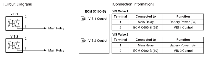
 Variable Intake Solenoid (VIS) Valve Description and Operation
Description
Variable Intake manifold Solenoid (VIS) valves are installed
on the intake manifold (VIS Valve 1) and the surge tank (VIS Valve 2).
VIS valves 1 and 2 control vacuum modulators that ...
 Variable Intake Solenoid (VIS) Valve Repair procedures
Inspection
1.
Turn the ignition switch OFF.
2.
Disconnect the VIS valve connector.
3.
Measure resistance between the VIS valve terminals 1 and 2.
4.
Check that the resistance is within ...
Other Information:
SS-A Solenoid Valve(ON/OFF) Description and Operation
Description
•
SS-A solenoid valve is ON/OFF type.
•
When TCM supplies variable current to solenoid valve, speed range is changed by operating the solenoid valve.
SS-A Soleno ...
AUX jack Components and Components Location
Components
...
Categories
- Home
- First Generation
- Second Generation
- Third generation
- Kia Sedona YP 2014-2026 Owners Manual
- Kia Sedona YP 2014-2026 Service Manual

Copyright © www.kisedona.com 2016-2026