 Kia Sedona: Components and Components Location
Third generation YP (2014-2025) / Kia Sedona YP Service Manual / Engine Control / Fuel System / Engine Control System / Components and Components Location
| Components Location |
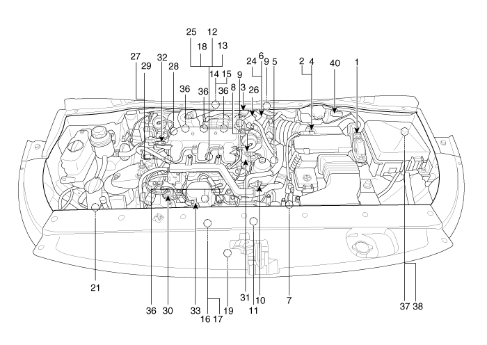
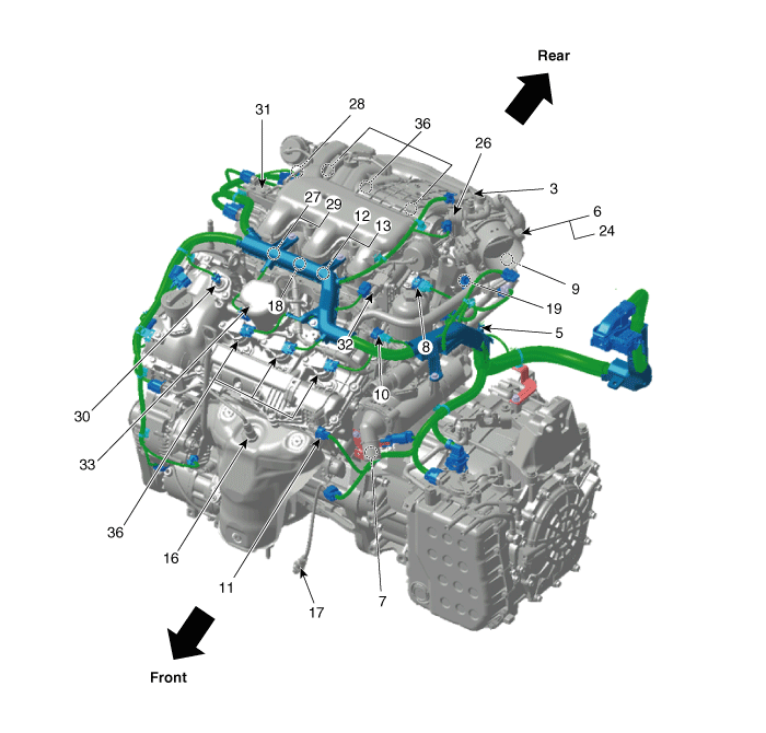
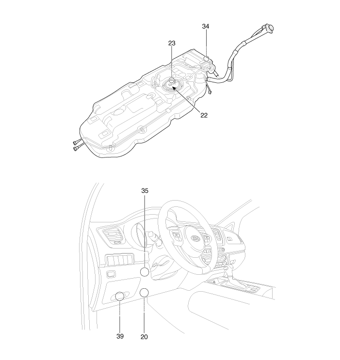
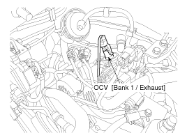
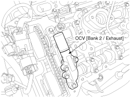
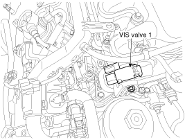
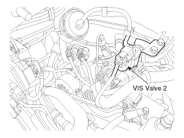
| 1. Engine Control Module (ECM) 2. Barometric Pressure Sensor (BPS) 3. Manifold Absolute Pressure Sensor (MAPS) 4. Intake Air Temperature Sensor (IATS) 5. Engine Coolant Temperature Sensor (ECTS) 6. Throttle Position Sensor (TPS) [integrated into ETC Module] 7. Crankshaft Position Sensor (CKPS) 8. Camshaft Position Sensor (CMPS) [Bank 1 / Intake] 9. Camshaft Position Sensor (CMPS) [Bank 1 / Exhaust] 10. Camshaft Position Sensor (CMPS) [Bank 2 / Intake] 11. Camshaft Position Sensor (CMPS) [Bank 2 / Exhaust] 12. Knock Sensor (KS) [Bank 1] 13. Knock Sensor (KS) [Bank 2] 14. Heated Oxygen Sensor (HO2S) [Bank 1 / Sensor 1] 15. Heated Oxygen Sensor (HO2S) [Bank 1 / Sensor 2] 16. Heated Oxygen Sensor (HO2S) [Bank 2 / Sensor 1] 17. Heated Oxygen Sensor (HO2S) [Bank 2 / Sensor 2] 18. Rail Pressure Sensor (RPS) 19. CVVT Oil Temperature Sensor (OTS) 20. Accelerator Position Sensor (APS) | 21. A/C Pressure Transducer (APT) 22. Fuel Tank Pressure Sensor (FTPS) 23. Fuel Level Sender (FLS) 24. ETC Motor [integrated into ETC Module] 25. Injector [Bank 1, Bank 2] 26. Purge Control Solenoid Valve (PCSV) 27. CVVT Oil Control Valve (OCV) [Bank 1 / Intake] 28. CVVT Oil Control Valve (OCV) [Bank 1 / Exhaust] 29. CVVT Oil Control Valve (OCV) [Bank 2 / Intake] 30. CVVT Oil Control Valve (OCV) [Bank 2 / Exhaust] 31. Variable Intake Solenoid (VIS) Valve 1 32. Variable Intake Solenoid (VIS) Valve 2 33. Fuel Pressure Control Valve (FPCV) 34. Canister Close Valve (CCV) 35. Injector drive Box (IDB) 36. Ignition Coil 37. Main Relay 38. Fuel Pump Relay 39. Data Link Connector (DLC) [16 Pin] 40. Multi-Purpose Check Connector [20 Pin] |
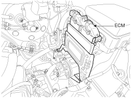
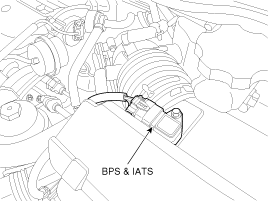
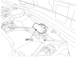
| 1. Engine Control Module (ECM) | 2. Barometric Pressure Sensor (BPS) 4. Intake Air Temperature Sensor (IATS) |
|
|
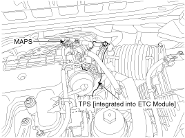
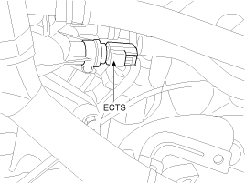
| 3. Manifold Absolute Pressure Sensor (MAPS) 6. Throttle Position Sensor (TPS) [integrated into ETC Module] | 5. Engine Coolant Temperature Sensor (ECTS) |
|
|
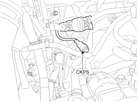
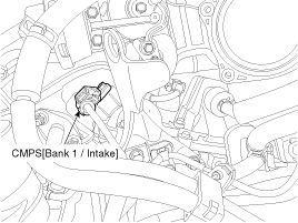
| 7. Crankshaft Position Sensor (CKPS) | 8. Camshaft Position Sensor (CMPS) [Bank 1 / Intake] |
|
|
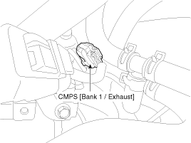
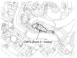
| 9. Camshaft Position Sensor (CMPS) [Bank 1 / Exhaust] | 10. Camshaft Position Sensor (CMPS) [Bank 2 / Intake] |
|
|
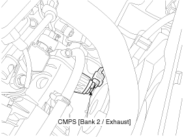
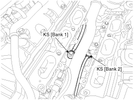
| 11. Camshaft Position Sensor (CMPS) [Bank 2 / Exhaust] | 12. Knock Sensor (KS) [Bank 1] 13. Knock Sensor (KS) [Bank 2] |
|
|
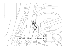
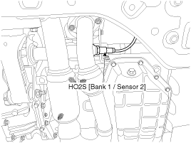
| 14. Heated Oxygen Sensor (HO2S) [Bank 1 / Sensor 1] | 15.Heated Oxygen Sensor (HO2S) [Bank 1 / Sensor 2] |
|
|
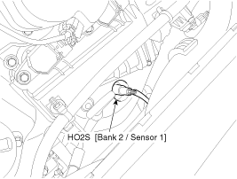
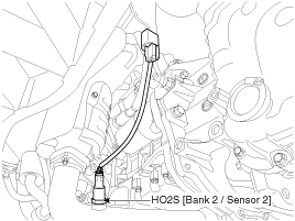
| 16. Heated Oxygen Sensor (HO2S) [Bank 2 / Sensor 1] | 17. Heated Oxygen Sensor (HO2S) [Bank 2 / Sensor 2] |
|
|
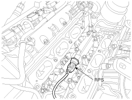
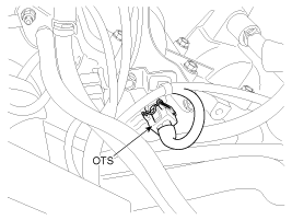
| 18. Rail Pressure Sensor (RPS) | 19. CVVT Oil Temperature Sensor (OTS) |
|
|
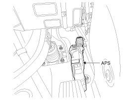
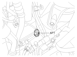
| 20. Accelerator Position Sensor (APS) | 21. A/C Pressure Transducer (APT) |
|
|
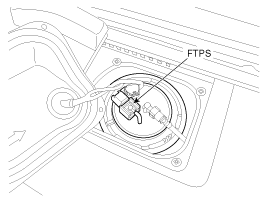
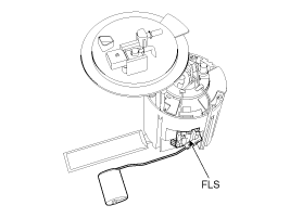
| 22. Fuel Tank Pressure Sensor (FTPS) | 23. Fuel Level Sender (FLS) |
|
|
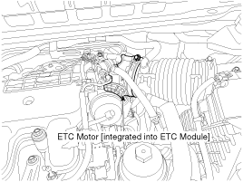
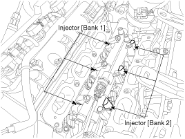
| 24. ETC Motor [integrated into ETC Module] | 25. Injector |
|
|
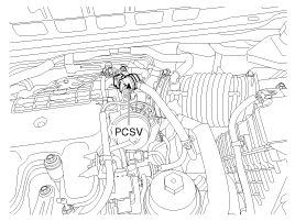
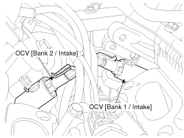
| 26. Purge Control Solenoid Valve (PCSV) | 27. CVVT Oil Control Valve (OCV) [Bank 1 / Intake] 29. CVVT Oil Control Valve (OCV) [Bank 2 / Intake] |
|
|
| 28. CVVT Oil Control Valve (OCV) [Bank 1 / Exhaust] | 30. CVVT Oil Control Valve (OCV) [Bank 2 / Exhaust] |
|
|
| 31. Variable Intake Solenoid (VIS) Valve 1 | 32. Variable Intake Solenoid (VIS) Valve 2 |
|
|
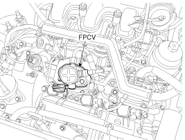
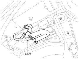
| 33. Fuel Pressure Control Valve (FPCV) | 34. Canister Close Valve (CCV) |
|
|
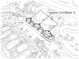
| 35. Injector drive Box (IDB) | 36. Ignition Coil [Bank 1] |
|
|
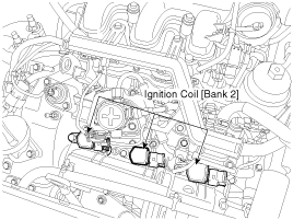
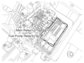
| 36. Ignition Coil [Bank 2] | 37. Main Relay (EMS Box) 38. Fuel Pump Relay (EMS Box) |
|
|
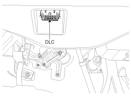
| 39. Data Link Connector (DLC) [16 Pin] | 40. Multi-Purpose Check Connector [20 Pin] |
|
|
 Description and Operation
OBD-II review
1. Overview
The California Air Resources Board (CARB) began regulation of
On Board Diagnostics (OBD) for vehicles sold in California beginning
with the 1988 model year. The first ...
Other Information:
ON
Redish orange
Press the ENGINE START/STOP button while it is in the ACC position without depressing
the brake pedal.
The warning lights can be checked before the engine is started. Do not leave ...
Troubleshooting
Troubleshooting
Trouble SymptomProbable causeRemedyVehicle pulls to one sideScoring of driveshaft ball jointReplaceWear, rattle or scoring of wheel bearingReplaceDefective front suspension and st ...
Categories
- Home
- First Generation
- Second Generation
- Third generation
- Kia Sedona YP 2014-2025 Owners Manual
- Kia Sedona YP 2014-2025 Service Manual
Copyright В© www.kisedona.com 2016-2025

