 Kia Sedona: Ignition Coil Repair procedures
Third generation YP (2014-2026) / Kia Sedona YP Service Manual / Engine Electrical System / Ignition System / Ignition Coil Repair procedures
| Removal |
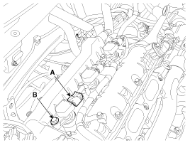
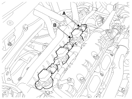
| Ignition coil (Cylinder #1) [Bank 1] |
| 1. |
Remove the surge tank.
(Refer to Engine Mechanical System - "Surge Tank") |
| 2. |
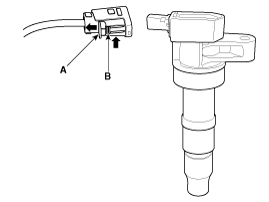
Disconnect the Ignition coil connector (A). |
| 3. |
Remove the ignition coil after loosening the mounting bolt (B).
|
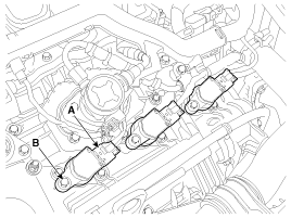
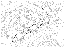
| Ignition coil (Cylinder #2) [Bank 2] |
| 1. |
Turn the ignition switch off and disconnect the battery negative (-) Terminal. |
| 2. |
Disconnect the Ignition coil connector (A). |
| 3. |
Remove the ignition coil after loosening the mounting bolt (B).
|
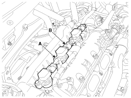
| Ignition coil (Cylinder #3) [Bank 1] |
| 1. |
Remove the surge tank.
(Refer to Engine Mechanical System - "Surge Tank") |
| 2. |
Disconnect the Ignition coil connector (A). |
| 3. |
Remove the ignition coil after loosening the mounting bolt (B).
|
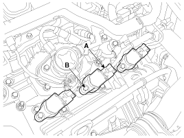
| Ignition coil (Cylinder #4) [Bank 2] |
| 1. |
Turn the ignition switch off and disconnect the battery negative (-) Terminal. |
| 2. |
Disconnect the Ignition coil connector (A). |
| 3. |
Remove the ignition coil after loosening the mounting bolt (B).
|
| Ignition coil (Cylinder #5) [Bank 1] |
| 1. |
Remove the surge tank.
(Refer to Engine Mechanical System - "Surge Tank") |
| 2. |
Disconnect the Ignition coil connector (A). |
| 3. |
Remove the ignition coil after loosening the mounting bolt (B).
|
| Ignition coil (Cylinder #6) [Bank 2] |
| 1. |
Turn the ignition switch off and disconnect the battery negative (-) Terminal. |
| 2. |
Disconnect the Ignition coil connector (A). |
| 3. |
Remove the ignition coil after loosening the mounting bolt (B).
|
| Installation |
| 1. |
Install in the reverse order of removal.
|
| Inspection |
| 1. |
Remove the ignition coil.
(Refer to "Removal") |
| 2. |
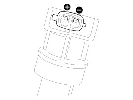
Measure the primary coil resistance between terminals (+) and (-).
|
 Ignition Coil Schematic Diagrams
Circuit Diagram
...
 Spark Plug Specifications
Specification
ItemSpecificationTypeSILZKR7B11Gap1.0 ~ 1.1 mm(0.0394 ~ 0.0433 in.)Insulation resistance (MΩ)10 or more
...
Other Information:
Ventilation
1. Set the mode to the position.
2. Set the air intake control to the outside (fresh) air position.
3. Set the temperature control to the desired position.
4. Set the fan speed control to the desi ...
Positive Crankcase Ventilation (PCV) Valve Description and Operation
Operation Principle
...
Categories
- Home
- First Generation
- Second Generation
- Third generation
- Kia Sedona YP 2014-2026 Owners Manual
- Kia Sedona YP 2014-2026 Service Manual
Copyright © www.kisedona.com 2016-2026

