 Kia Sedona: Front Door Latch Repair procedures
Third generation YP (2014-2026) / Kia Sedona YP Service Manual / Body (Interior and Exterior) / Front Door / Front Door Latch Repair procedures
| Replacement |
| 1. |
Remove the front door module.
(Refer to Front Door - "Front Door Module") |
| 2. |
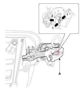
Remove the front door outside handle base (A) by pushing in the lock pins located in the back.
|
| 3. |
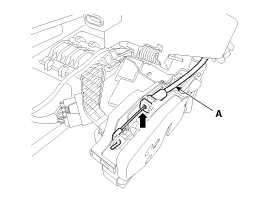
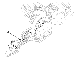
Remove the front door outside handle cable (A).
|
| 4. |
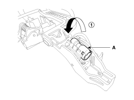
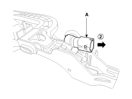
To remove the front door outside handle base connector (A), turn it counter clockwise and pull it forward.
|
| 5. |
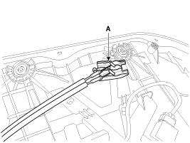
Remove the front door outside handle connector wiring harness (A).
|
| 6. |
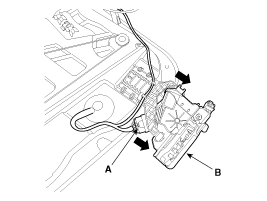
Disconnect the front door latch connector (A). |
| 7. |
Remove the front door latch assembly (B) by pulling it in the direction of the arrow.
|
| 8. |
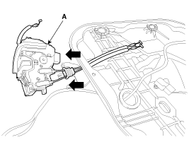
Disconnect the front door latch cage (A).
|
| 9. |
Remove the front door inside handle cable (A) by pushing it backward.
|
| 10. |
Install in the reverse order of removal.
|
 Front Door Latch Components and Components Location
Component Location
1. Front door latch
...
 Front Door Belt Outside Weatherstrip Repair procedures
Replacement
1.
Pull down front door window glass by pressing the power window glass switch.
2.
After loosening the mounting screws, remove the front door belt outside weatherstrip (A).
3.
...
Other Information:
Evaporator Temperature Sensor Repair procedures
Inspection
1.
Turn the ignition switch OFF.
2.
Disconnect the evaporator temperature sensor connector.
3.
Measure resistance between terminals “+” and “-” of the evaporator tempera ...
Fuel Filler Door Release Actuator Repair procedures
Removal
Fuel Filler Door Release Actuator
1.
Disconnect the negative (-) battery terminal.
2.
Remove the luggage side trim [LH].
(Refer to Body - "Luggage Side Trim")
3.
Disconnect the c ...
Categories
- Home
- First Generation
- Second Generation
- Third generation
- Kia Sedona YP 2014-2026 Owners Manual
- Kia Sedona YP 2014-2026 Service Manual
Copyright © www.kisedona.com 2016-2026

