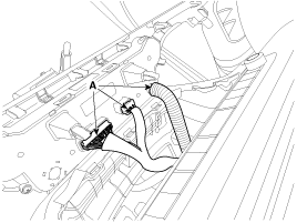
 Kia Sedona: Center Fascia Panel Repair procedures
Third generation YP (2014-2025) / Kia Sedona YP Service Manual / Body (Interior and Exterior) / Crash Pad / Center Fascia Panel Repair procedures
| Replacement |
| [Center fascia upper panel] |
Put on gloves to protect your hands. |
|
| 1. |
Lower the steering wheel. |
| 2. |
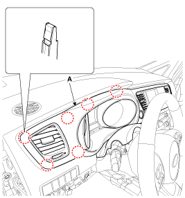
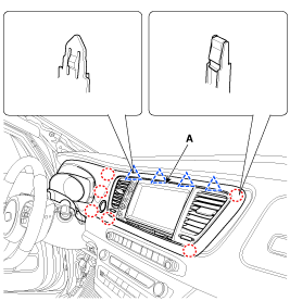
Using a screwdriver or remover, remove the center fascia upper panel (A).
|
| 3. |
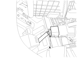
Disconnect the start/stop button connector (A).
|
| 4. |
Install in the reverse order of removal. |
| [Center fascia lower panel] |
Put on gloves to protect your hands. |
|
| 1. |
Remove the crash pad lower panel.
(Refer to Crash Pad - "Center Fascia Panel ") |
| 2. |
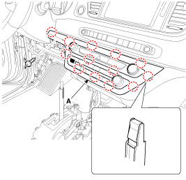
Loosen the mounting screws and remove the center fascia lower panel (A).
|
| 3. |
Disconnect the controller connector (A).
|
| 4. |
Install in the reverse order of removal. |
 Center Fascia Panel Components and Components Location
Component Location
1. Center fascia upper panel2. Center fascia lower panel
...
 Crash Pad Lower Panel Components and Components Location
Component Location
1. Crash pad lower panel
...
Other Information:
Side repeater lamp replacement
If the light bulb does not operate,have the vehicle checked by an authorized
Kia dealer.
A skilled technician should check or repair the side repeater lamp, for it may
damage related out side m ...
Intake Manifold Repair procedures
Removal and Installation
1.
Remove the engine cover.
(Refer to Engine and Transaxle Assembly - "Engine Cover")
2.
Remove the engine room under cover.
(Refer to Engine and Transaxle Assembly ...
Categories
- Home
- First Generation
- Second Generation
- Third generation
- Kia Sedona YP 2014-2025 Owners Manual
- Kia Sedona YP 2014-2025 Service Manual
Copyright © www.kisedona.com 2016-2025


