 Kia Sedona: Accelerator Position Sensor (APS) Repair procedures
Third generation YP (2014-2026) / Kia Sedona YP Service Manual / Engine Control / Fuel System / Engine Control System / Accelerator Position Sensor (APS) Repair procedures
| Inspection |
| 1. |
Connect the GDS on the Data Link Connector (DLC). |
| 2. |
Turn the ignition switch ON. |
| 3. |
Measure the output voltage of the APS 1 and 2 at C.T and W.O.T.
| |||||||||||
| Removal |
| 1. |
Turn the ignition switch OFF and disconnect the negative (-) battery terminal. |
| 2. |
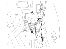
Disconnect the accelerator position sensor connector (A). |
| 3. |
Remove the installation nuts (B) and then remove the accelerator pedal module.
|
| Installation |
| 1. |
Install in the reverse order of removal.
|
 Accelerator Position Sensor (APS) Schematic Diagrams
Circuit Diagram
...
 Fuel Tank Pressure Sensor (FTPS) Specifications
Specification
ItemSpecificationSupply Voltage (V)5Operation Voltage (V)4.75 ~ 5.25
Pressure [kPa (kgf/cm², psi)]Output Voltage (V) [Ref=5V]-6.67 (-0.06, -0.97)0.502.5+6.67 (0.068, 0.97)4.5
...
Other Information:
CVVT & Camshaft Repair procedures
Removal
Continuous Variable Valve Timing (CVVT)
1.
Remove the timing chain.
(Refer to Timing System - "Timing Chain")
2.
Remove the CVVT assembly.
•
A: LH exhaust CVVT
•
...
Vehicle handling instructions
As with other vehicles of this type, failure to operate this vehicle correctly
may result in loss of control, an accident or vehicle rollover.
Specific design characteristics (higher ground clearan ...
Categories
- Home
- First Generation
- Second Generation
- Third generation
- Kia Sedona YP 2014-2026 Owners Manual
- Kia Sedona YP 2014-2026 Service Manual
Copyright © www.kisedona.com 2016-2026

