 Kia Sedona: Intake Air Temperature Sensor (IATS) Schematic Diagrams
Third generation YP (2014-2026) / Kia Sedona YP Service Manual / Engine Control / Fuel System / Engine Control System / Intake Air Temperature Sensor (IATS) Schematic Diagrams
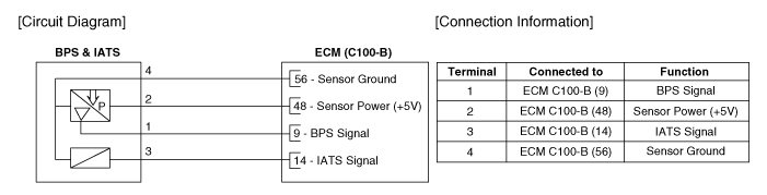
| Circuit Diagram |
 Intake Air Temperature Sensor (IATS) Description and Operation
Description
Integrated into the Barometric Pressure Sensor (BPS), the
Intake Air Temperature Sensor (IATS) detects the intake air temperature.
To calculate precise air quantity, correction of th ...
 Intake Air Temperature Sensor (IATS) Repair procedures
Inspection
1.
Turn the ignition switch OFF.
2.
Disconnect the IATS connector.
3.
Measure resistance between the IATS terminals 3 and 4.
4.
Check that the resistance is within the speci ...
Other Information:
Battery Sensor Repair procedures
Removal
1.
Turn the ignition switch OFF.
2.
Disconnect the battery negative (-) terminal (A).
Battery negative (-) terminal tightening nut :
4.0 ~ 6.0 N.m (0.4 ~ 0.6 kgf.m, 3.0 ~ 4.4 lb-ft ...
Description and Operation
Description of ESC
Electronic Stability Control (ESC) recognizes critical
driving conditions, such as panic reactions in dangerous situations, and
stabilizes the vehicle by wheel-individual bra ...
Categories
- Home
- First Generation
- Second Generation
- Third generation
- Kia Sedona YP 2014-2026 Owners Manual
- Kia Sedona YP 2014-2026 Service Manual

Copyright © www.kisedona.com 2016-2026