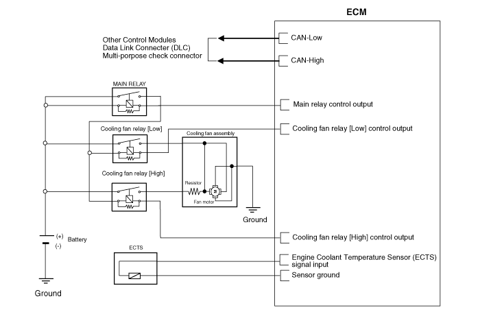
 Kia Sedona: Cooling Fan Schematic Diagrams
Third generation YP (2014-2025) / Kia Sedona YP Service Manual / Engine Mechanical System / Cooling System / Cooling Fan Schematic Diagrams
| Circuit Diagram |

 Cooling Fan Specifications
Specifications
ItemSpecificationFan typePULLERFan speed controlResistorAir flow rate [㎥/h (yd³/h)]2,650 (3,466) - 8% min.Fan speed (rpm)1,980 ± 8%Current (A)23.3 + 10% max.
...
 Cooling Fan Repair procedures
Removal and Installation
1.
Disconnect the battery negative terminal.
2.
Remove the air duct (A).
3.
Remove the front bumper cover.
(Refer to Body - "Front Bumper Cover")
4.
Disconnec ...
Other Information:
Rear Bumper beam Assembly Repair procedures
Replacement
•
When prying with a flat-tip screwdriver, wrap it with
protective tape, and apply protective tape around the related parts, to
prevent damage. ...
Radiator Grill Repair procedures
Replacement
Put on gloves to protect your hands.
•
When prying with a flat-tip screwdriver, wrap it with
protective tape, an ...
Categories
- Home
- First Generation
- Second Generation
- Third generation
- Kia Sedona YP 2014-2025 Owners Manual
- Kia Sedona YP 2014-2025 Service Manual
Copyright © www.kisedona.com 2016-2025
