
 Kia Sedona: Heated Oxygen Sensor (HO2S) Repair procedures
Third generation YP (2014-2026) / Kia Sedona YP Service Manual / Engine Control / Fuel System / Engine Control System / Heated Oxygen Sensor (HO2S) Repair procedures
| Inspection |
| 1. |
Turn the ignition switch OFF. |
| 2. |
Disconnect the HO2S connector. |
| 3. |
Measure resistance between the HO2S terminals 3 and 4. |
| 4. |
Check that the resistance is within the specification.
|
| Removal |
Note that the SST (Part No : 09392-1Y100 or 09392-2H100) is used when removing the heated oxygen sensor. |

| [Bank 1/Sensor 1] |
| 1. |
Turn the ignition switch OFF and disconnect the battery negative (-) terminal. |
| 2. |
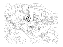
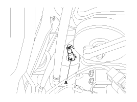
Disconnect the connector (A).
|
| 3. |
Remove the heated oxygen sensor (A).
|
| [Bank 1/Sensor 2] |
| 1. |
Turn the ignition switch OFF and disconnect the battery negative (-) terminal. |
| 2. |
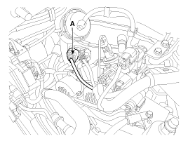
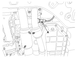
Disconnect the connector (A).
|
| 3. |
Remove the heated oxygen sensor (A).
|
| [Bank 2/Sensor 1] |
| 1. |
Turn the ignition switch OFF and disconnect the battery negative (-) terminal. |
| 2. |
Disconnect the connector (A).
|
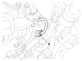
| 3. |
Remove the heated oxygen sensor (A).
|
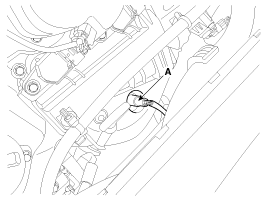
| [Bank 2/Sensor 2] |
| 1. |
Turn the ignition switch OFF and disconnect the battery negative (-) terminal. |
| 2. |
Disconnect the connector (A). |
| 3. |
Remove the heated oxygen sensor (B).
|
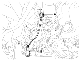
| Installation |
|
Note that the SST (Part No : 09392-1Y100 or 09392-2H100) is used when removing the heated oxygen sensor. |
| 1. |
Install in the reverse order of removal.
|
 Heated Oxygen Sensor (HO2S) Schematic Diagrams
Circuit Diagram
...
 Heated Oxygen Sensor (HO2S) Troubleshooting
Wave Form
...
Other Information:
Smart Cruise Control Unit Schematic Diagrams
Circuit Diagram
...
Front Disc Brake Components and Components Location
Components
1. Guide rod bolt2. Bleed screw3. Caliper carrier4. Caliper body5. Inner pad shim6. Brake pad7. Pad retainer
...
Categories
- Home
- First Generation
- Second Generation
- Third generation
- Kia Sedona YP 2014-2026 Owners Manual
- Kia Sedona YP 2014-2026 Service Manual

Copyright © www.kisedona.com 2016-2026