
 Kia Sedona: Injector Drive Box (IDB) Schematic Diagrams
Third generation YP (2014-2026) / Kia Sedona YP Service Manual / Engine Control / Fuel System / Engine Control System / Injector Drive Box (IDB) Schematic Diagrams
| IDB terminal and In/Output |
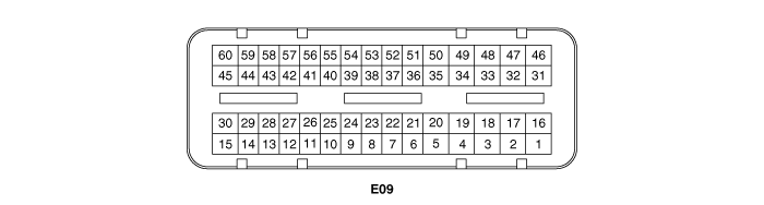
| IDB terminal function |
Connector [E09]
| Pin No. | Description | Connected to |
| 1 | - | |
| 2 | - | |
| 3 | - | |
| 4 | - | |
| 5 | - | |
| 6 | - | |
| 7 | - | |
| 8 | - | |
| 9 | - | |
| 10 | - | |
| 11 | - | |
| 12 | - | |
| 13 | - | |
| 14 | - | |
| 15 | - | |
| 16 | Injector (Cylinder #3) [Low] control output | Injector (Cylinder #3) |
| 17 | Injector (Cylinder #6) [Low] control output | Injector (Cylinder #6) |
| 18 | Injector (Cylinder #6) [High] control output | Injector (Cylinder #6) |
| 19 | Injector (Cylinder #2) [Low] control output | Injector (Cylinder #2) |
| 20 | Injector (Cylinder #5) [Low] control output | Injector (Cylinder #5) |
| 21 | - | |
| 22 | Injector (Cylinder #2) signal input | Engine Control Module (ECM) |
| 23 | Injector (Cylinder #5) signal input | Engine Control Module (ECM) |
| 24 | - | |
| 25 | Fuel Pressure Control Valve (FPCV) logic input | Engine Control Module (ECM) |
| 26 | CCP-CAN [Low] | Other control module, Data Link Connector (DLC), Multi-purpose check connector |
| 27 | CCP-CAN [High] | Other control module, Data Link Connector (DLC), Multi-purpose check connector |
| 28 | Battery power (B+) | Ignition switch |
| 29 | Battery power (B+) | Main relay |
| 30 | Battery power (B+) | Main relay |
| 31 | Injector (Cylinder #4) [High] control output | Injector (Cylinder #4) |
| 32 | Injector (Cylinder #1) [High] control output | Injector (Cylinder #1) |
| 33 | Injector (Cylinder #3) [High] control output | Injector (Cylinder #3) |
| 34 | Injector (Cylinder #2) [High] control output | Injector (Cylinder #2) |
| 35 | Injector (Cylinder #5) [High] control output | Injector (Cylinder #5) |
| 36 | - | |
| 37 | - | |
| 38 | Injector (Cylinder #3) signal input | Engine Control Module (ECM) |
| 39 | - | |
| 40 | Injector (Cylinder #6) signal input | Engine Control Module (ECM) |
| 41 | Injector (Cylinder #4) signal input | Engine Control Module (ECM) |
| 42 | Battery power (B+) | Ignition switch |
| 43 | Battery power (B+) | Main relay |
| 44 | Battery power (B+) | Main relay |
| 45 | Fuel Pressure Control Valve (FPCV) [High] control output | Fuel Pressure Control Valve (FPCV) |
| 46 | Injector (Cylinder #4) [Low] control output | Injector (Cylinder #4) |
| 47 | Injector (Cylinder #1) [Low] control output | Injector (Cylinder #1) |
| 48 | ECM ground | Chassis ground |
| 49 | ECM ground | Chassis ground |
| 50 | ECM ground | Chassis ground |
| 51 | - | |
| 52 | ECM ground | Chassis ground |
| 53 | ECM ground | Chassis ground |
| 54 | - | |
| 55 | Injector (Cylinder #1) signal input | Engine Control Module (ECM) |
| 56 | - | |
| 57 | - | |
| 58 | - | |
| 59 | Battery power (B+) | Main relay |
| 60 | Fuel Pressure Control Valve (FPCV) [Low] control output | Fuel Pressure Control Valve (FPCV) |
| IDB Terminal input/output signal |
Connector [E09]
| Pin No. | Description | Condition | Type | Level |
| 1 | - | | | |
| 2 | - | | | |
| 3 | - | | | |
| 4 | - | | | |
| 5 | - | | | |
| 6 | - | | | |
| 7 | - | | | |
| 8 | - | | | |
| 9 | - | | | |
| 10 | - | | | |
| 11 | - | | | |
| 12 | - | | | |
| 13 | - | | | |
| 14 | - | | | |
| 15 | - | | | |
| 16 | Injector (Cylinder #3) [Low] control output | Idle | Pulse | High: Battery voltage |
| Relay ON | Low: Max. 1.0V | |||
| 17 | Injector (Cylinder #6) [Low] control output | Idle | Pulse | High: Battery voltage |
| Relay ON | Low: Max. 1.0V | |||
| 18 | Injector (Cylinder #6) [High] control output | Idle | Pulse | High: Battery voltage ~ 80V |
| Relay ON | Low: Battery voltage | |||
| 19 | Injector (Cylinder #2) [Low] control output | Idle | Pulse | High: Battery voltage |
| Relay ON | Low: Max. 1.0V | |||
| 20 | Injector (Cylinder #5) [Low] control output | Idle | Pulse | High: Battery voltage |
| Relay ON | Low: Max. 1.0V | |||
| 21 | - | | | |
| 22 | Injector (Cylinder #2) signal input | Idle | Pulse | High: Battery voltage |
| Low: Max. 1.0V | ||||
| 23 | Injector (Cylinder #5) signal input | Idle | Pulse | High: Battery voltage |
| Low: Max. 1.0V | ||||
| 24 | - | | | |
| 25 | Fuel Pressure Control Valve (FPCV) logic input | | | |
| | | | ||
| 26 | CCP-CAN [Low] | Recessive | Pulse | 2.0 ~ 3.0V |
| Dominant | 2.75 ~ 4.5V | |||
| 27 | CCP-CAN [High] | Recessive | Pulse | 2.0 ~ 3.0V |
| Dominant | 2.75 ~ 4.5V | |||
| 28 | Battery power (B+) | IG OFF | DC voltage | Max. 0.5V |
| IG ON | Battery voltage | |||
| 29 | Battery power (B+) | IG OFF | DC voltage | Max. 0.5V |
| IG ON | Battery voltage | |||
| 30 | Battery power (B+) | IG OFF | DC voltage | Max. 0.5V |
| IG ON | Battery voltage | |||
| 31 | Injector (Cylinder #4) [High] control output | Idle | Pulse | High: Battery voltage ~ 80V |
| Relay ON | Low: Battery voltage | |||
| 32 | Injector (Cylinder #1) [High] control output | Idle | Pulse | High: Battery voltage ~ 80V |
| Relay ON | Low: Battery voltage | |||
| 33 | Injector (Cylinder #3) [High] control output | Idle | Pulse | High: Battery voltage ~ 80V |
| Relay ON | Low: Battery voltage | |||
| 34 | Injector (Cylinder #2) [High] control output | Idle | Pulse | High: Battery voltage ~ 80V |
| Relay ON | Low: Battery voltage | |||
| 35 | Injector (Cylinder #5) [High] control output | Idle | Pulse | High: Battery voltage ~ 80V |
| Relay ON | Low: Battery voltage | |||
| 36 | - | | | |
| 37 | - | | | |
| 38 | Injector (Cylinder #3) signal input | Idle | Pulse | High: Battery voltage |
| Low: Max. 1.0V | ||||
| 39 | - | | | |
| 40 | Injector (Cylinder #6) signal input | Idle | Pulse | High: Battery voltage |
| Low: Max. 1.0V | ||||
| 41 | Injector (Cylinder #4) signal input | Idle | Pulse | High: Battery voltage |
| Low: Max. 1.0V | ||||
| 42 | Battery power (B+) | IG OFF | DC voltage | Max. 0.5V |
| IG ON | Battery voltage | |||
| 43 | Battery power (B+) | IG OFF | DC voltage | Max. 0.5V |
| IG ON | Battery voltage | |||
| 44 | Battery power (B+) | IG OFF | DC voltage | Max. 0.5V |
| IG ON | Battery voltage | |||
| 45 | Fuel Pressure Control Valve (FPCV) [High] control output | Idle | DC voltage | Battery voltage |
| Max. 1.0V | ||||
| 46 | Injector (Cylinder #4) [Low] control output | Idle | Pulse | High: Battery voltage |
| Relay ON | Low: Max. 1.0V | |||
| 47 | Injector (Cylinder #1) [Low] control output | Idle | Pulse | High: Battery voltage |
| Relay ON | Low: Max. 1.0V | |||
| 48 | ECM ground | Idle | DC voltage | Max. 50mV |
| 49 | ECM ground | Idle | DC voltage | Max. 50mV |
| 50 | ECM ground | Idle | DC voltage | Max. 50mV |
| 51 | - | | | |
| 52 | ECM ground | Idle | DC voltage | Max. 50mV |
| 53 | ECM ground | Idle | DC voltage | Max. 50mV |
| 54 | - | | | |
| 55 | Injector (Cylinder #1) signal input | Idle | Pulse | High: Battery voltage |
| Low: Max. 1.0V | ||||
| 56 | - | | | |
| 57 | - | | | |
| 58 | - | | | |
| 59 | Battery power (B+) | IG OFF | DC voltage | Max. 0.5V |
| IG ON | Battery voltage | |||
| 60 | Fuel Pressure Control Valve (FPCV) [Low] control output | Idle | DC voltage | Battery voltage |
| Max. 1.0V |
| Circuit Diagram |
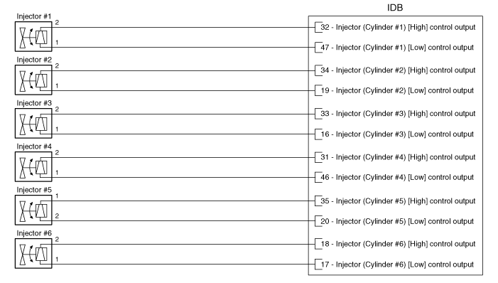
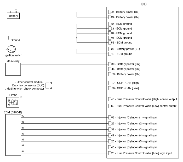
 Engine Control Module (ECM) Repair procedures
Removal
1.
Turn ignition switch OFF and disconnect the negative (-) battery terminal.
2.
Remove the battery.
(Refer to Engine Electrical System - "Battery")
3.
Remove the air cleaner asse ...
 Injector Drive Box (IDB) Repair procedures
Removal
1.
Turn the ignition switch off and disconnect the battery negative (-) Terminal.
2.
Remove the mounting nuts (A) and disconnect the connector (B), and then remove the injector drive b ...
Other Information:
Front Door Belt Outside Weatherstrip Repair procedures
Replacement
1.
Pull down front door window glass by pressing the power window glass switch.
2.
After loosening the mounting screws, remove the front door belt outside weatherstrip (A).
3.
...
Accelerator Position Sensor (APS) Description and Operation
Description
Accelerator Position Sensor (APS), installed on the
accelerator pedal module, detects the rotation angle of the accelerator
pedal. The APS, one of the most important sensors in engi ...
Categories
- Home
- First Generation
- Second Generation
- Third generation
- Kia Sedona YP 2014-2026 Owners Manual
- Kia Sedona YP 2014-2026 Service Manual

Copyright © www.kisedona.com 2016-2026