 Kia Sedona: Starter Schematic Diagrams
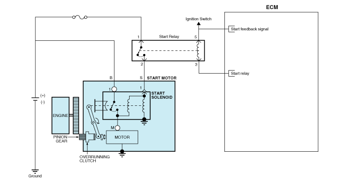
Third generation YP (2014-2026) / Kia Sedona YP Service Manual / Engine Electrical System / Starting System / Starter Schematic Diagrams
| Circuit Diagram |
 Starter Description and Operation
Description
The starting system includes the battery, starter, solenoid
switch, ignition switch, inhibitor switch (A/T), clutch pedal switch
(M/T), ignition lock switch, connection wires and th ...
 Starter Repair procedures
Removal
1.
Turn the ignition switch OFF and disconnect the battery negative (-) terminal.
2.
Remove the engine room under cover.
(Refer to Engine Mechanical System - "Engine Room Under Cover" ...
Other Information:
Temperature control
The temperature control knob allows you to control the temperature of the air
flowing from the ventilation system. To change the air temperature in the passenger
compartment, turn the knob to th ...
TPMS Sensor Description and Operation
Description
1.
Function
•
By detecting the pressure, temperature, acceleration, and battery condition, transmit information to ECU by a wireless RF.
•
2.
Structure and f ...
Categories
- Home
- First Generation
- Second Generation
- Third generation
- Kia Sedona YP 2014-2026 Owners Manual
- Kia Sedona YP 2014-2026 Service Manual

Copyright © www.kisedona.com 2016-2026