 Kia Sedona: Seat Heater Schematic Diagrams
Third generation YP (2014-2026) / Kia Sedona YP Service Manual / Body Electrical System / Seat Electrical / Seat Heater Schematic Diagrams
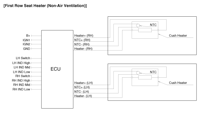
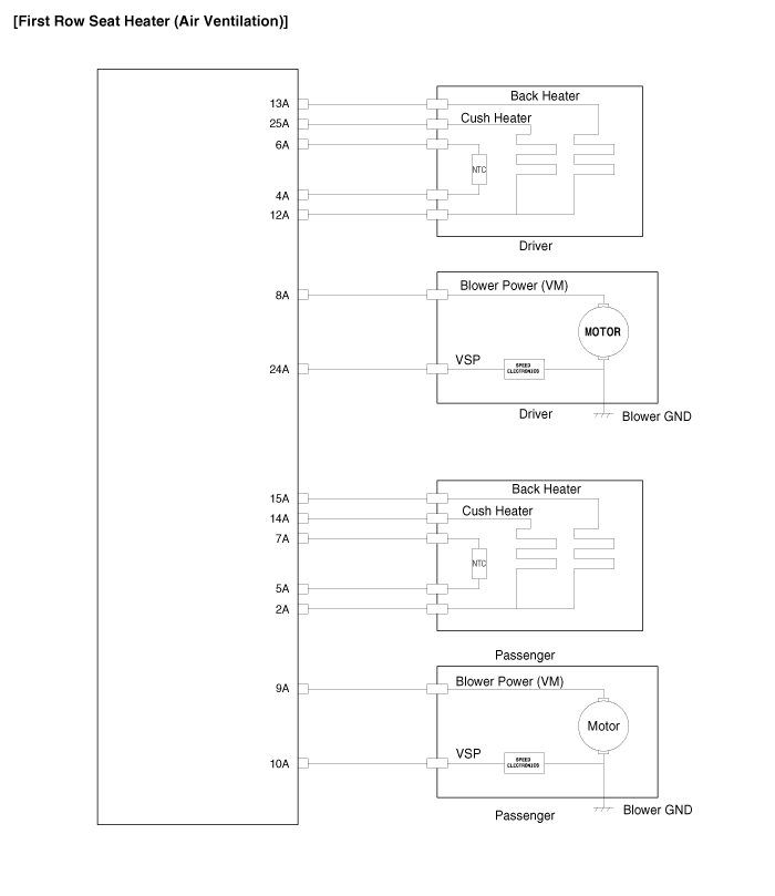
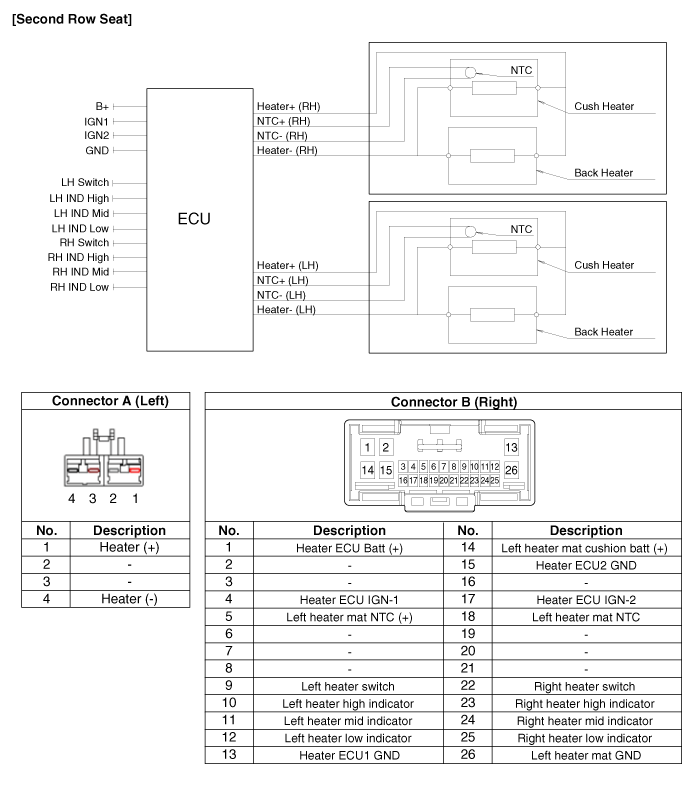
| Circuit Diagram |


Connector Pin Information
| No. | Description | No. | Description |
| 1 | Power Seat Batt (+) | 18 | Left NTC (+) |
| 2 | Left air ventilation/heater cushion batt (+) | 19 | Air ventilation/heater ECU batt (+) |
| 3 | Left air ventilation/heater back batt (+) | 20 | Left blower speed |
| 4 | Left blower power batt (+) | 21 | - |
| 5 | Left heater switch | 22 | Right heater switch |
| 6 | Left heater high indicator | 23 | Right heater high indicator |
| 7 | Left heater mid indicator | 24 | Right heater mid indicator |
| 8 | Left heater low indicator | 25 | Right heater low indicator |
| 9 | Left air ventilation switch | 26 | Right air ventilation switch |
| 10 | Left air ventilation high indicator | 27 | Right air ventilation high indicator |
| 11 | Left air ventilation mid indicator | 28 | Right air ventilation mid indicator |
| 12 | Left air ventilation low indicator | 29 | Right air ventilation low indicator |
| 13 | Air ventilation/heater ECU IGN2 | 30 | Spare |
| 14 | Air ventilation/heater ECU GND | 31 | Heater ECU2 GND |
| 15 | Left NTC | 32 | Left air ventilation/heater mat GND |
| 16 | Power seat GND | 33 | Right blower GND |
| 17 | Air ventilation/heater ECU IGN1 | 34 | Left blower GND |

 Seat Heater Components and Components Location
Components
...
 Seat Heater Repair procedures
Inspection
First Row Seat Heater
1.
Check for continuity and measure the resistance between terminals No 3 and No 6.
Standard value
Driver / Assists (cushion) : 3.23Ω±10%
Driver / Assist ...
Other Information:
Rear Disc Brake Components and Components Location
Components
1. Guide rod bolt2. Bleed screw3. Caliper carrier4. Caliper body5. Inner pad shim6. Brake pad7. Pad retainer
...
Muffler Components and Components Location
Components
1. Gasket2. Hanger3. Front muffler4. Catalytic converter & Center muffler assembly5. Rear muffler6. Tail muffler
...
Categories
- Home
- First Generation
- Second Generation
- Third generation
- Kia Sedona YP 2014-2026 Owners Manual
- Kia Sedona YP 2014-2026 Service Manual
Copyright © www.kisedona.com 2016-2026
