 Kia Sedona: Cylinder Head Cover Repair procedures
Third generation YP (2014-2026) / Kia Sedona YP Service Manual / Engine Mechanical System / Cylinder Head Assembly / Cylinder Head Cover Repair procedures
| Removal |
[LH Cylinder Head Cover]
| 1. |
Remove the air duct.
(Refer to Intake And Exhaust System - "Air Cleaner") |
| 2. |
Remove the battery.
(Refer to Engine Electrical System - "Battery") |
| 3. |
Remove the engine cover.
(Refer to Engine And Transaxle Assembly - "Engine Cover") |
| 4. |
Remove the air cleaner assembly.
(Refer to Intake And Exhaust System - "Air Cleaner") |
| 5. |
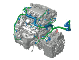
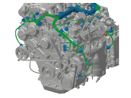
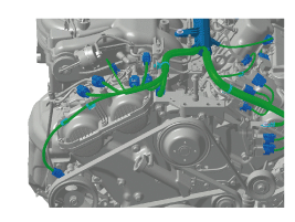
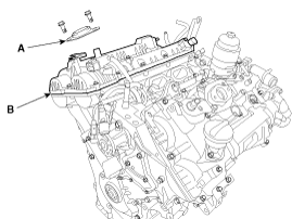
Disconnect the control wiring harness connectors and
fasteners and remove the wiring harness protectors from the LH cylinder
head cover.
|
| 6. |
Remove the LH ignition coils.
(Refer to Engine Electrical System - "Ignition Coil") |
| 7. |
Remove the surge tank.
(Refer to Intake And Exhaust System - "Surge Tank") |
| 8. |
Remove the intake manifold.
(Refer to Intake And Exhaust System - "Intake Manifold") |
| 9. |
Remove the high pressure fuel pump.
(Refer to Fuel System - "High Pressure Fuel Pump") |
| 10. |
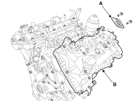
Remove the LH cylinder head cover.
|
[RH Cylinder Head Cover]
| 1. |
Remove the air duct.
(Refer to Intake And Exhaust System - "Air Cleaner") |
| 2. |
Remove the battery.
(Refer to Engine Electrical System - "Battery") |
| 3. |
Remove the engine cover.
(Refer to Engine And Transmission Assembly - "Engine Cover") |
| 4. |
Remove the air cleaner assembly.
(Refer to Intake And Exhaust System - "Air Cleaner") |
| 5. |
Disconnect the control wiring harness connectors and
fasteners and remove the wiring harness protectors from the LH cylinder
head cover.
|
| 6. |
Remove the surge tank.
(Refer to Intake And Exhaust System - "Surge Tank") |
| 7. |
Remove the LH ignition coils.
(Refer to Engine Electrical System - "Ignition Coil") |
| 8. |
Remove the RH cylinder head cover.
|
| Installation |
[LH Cylinder Head Cover]
| 1. |
Install the LH cylinder head cover.
|
| 2. |
Install the rest of the parts in the reverse order of removal. |
[RH Cylinder Head Cover]
| 1. |
Install the RH cylinder head cover.
|
| 2. |
Install the rest of the parts in the reverse order of removal. |
 Valve Clearance Adjustment
Valve Clearance Inspection and Adjustment
Inspect and adjust the valve clearance when the engine is
cold (Engine coolant temperature : 20°C [68°F]) and cylinder hea ...
 CVVT & Camshaft Components and Components Location
Components
1. RH exhaust camshaft2. RH intake camshaft3. LH intake camshaft4. LH exhaust camshaft
1. RH exhaust CVVT2. RH intake CVVT3. LH intake CVVT4. LH exhaust CVVT
...
Other Information:
RCTA (Rear Cross Traffic Alert)
When your vehicle moves backwards from a parking position, the sensor detects
approaching vehicles to the left or right side direction and gives information to
the driver. ...
Torque Converter Control Solenoid Valve (T/CON_VFS) Components and Components Location
Component Location
1. Torque Converter Control Solenoid Valve (T/CON_VFS) ...
Categories
- Home
- First Generation
- Second Generation
- Third generation
- Kia Sedona YP 2014-2026 Owners Manual
- Kia Sedona YP 2014-2026 Service Manual
Copyright © www.kisedona.com 2016-2026

