 Kia Sedona: Compressor Repair procedures
Third generation YP (2014-2026) / Kia Sedona YP Service Manual / Heating,Ventilation And Air Conditioning / Air conditioning System / Compressor Repair procedures
| Removal |
| 1. |
If the compressor is marginally operable, run the engine at
idle speed, and let the air conditioning work for a few minutes, then
shut the engine off. |
| 2. |
Disconnect the negative (-) battery terminal. |
| 3. |
Recover the refrigerant with a recovery/charging station. |
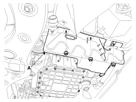
| 4. |
Remove the engine room right side under cover (A) by loosening the mounting nuts.
|
| 5. |
Loosen the drive belt.
(Refer to Engine Mechanical System - " Drive Belt") |
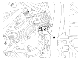
| 6. |
Disconnect the compressor switch connector (A).
|
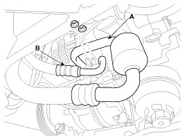
| 7. |
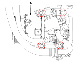
Remove the bolts, then disconnect the suction line (A) and discharge line (B) from the compressor.
|

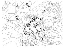
| 8. |
Remove the compressor (A) by loosening the mounting bolts.
|
| Installation |
| 1. |
Make sure that the compressor (A) mounting bolt of the
correct length is screwed in. Tighten the mounting bolts in the
specified tightening order.
|
| 2. |
Install in the reverse order of removal.
|
| Inspection |
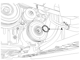
| 1. |
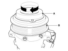
Check the plated parts of the limiter & hub assembly (A)
for color changes, peeling or other damage. If there is damage, replace
the assembly. |
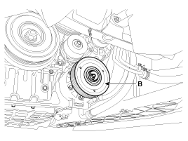
| 2. |
Check the pulley (B) bearing play and drag by rotating the
pulley by hand. Replace the pulley with a new one if it is noisy or has
excessive play/drag.
|
| Electronic Control Valve Compressor Inspection (Tester) |
| 1. |
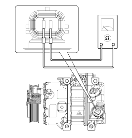
Disconnect the ECV connector from the compressor. |
| 2. |
Measure resistance between terminal "+" and "-" of the ECV connector.
|

| Electronic Control Valve Compressor Inspection (GDS) |
Compressor type: Fixed type compressor, External control valve, Internal control valve.
In cases of fixed type and internal control valve, it is possible to inspect compressor''s operation with clutch noise.
When it comes to External control valve, however, it cannot be checked in this way as it does not have a clutch.
So, ECV should be inspected by GDS in the following procedure:
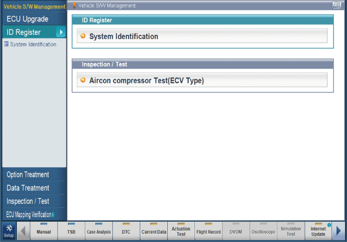
| 1. |
Connect GDS to the vehicle and select ''Aircon Compressor Test(ECV type)''
[ECV1]
|
| 2. |
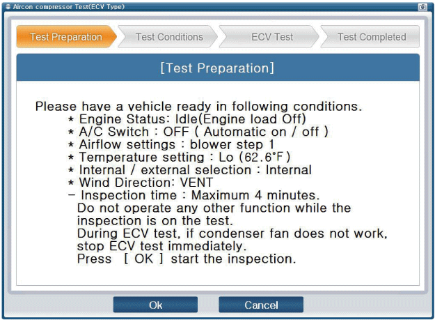
Make the vehicle ready as the GDS instruction on the monitor. (Turn off A/C ''switch'' only)
[ECV2]
[ECV3]
|

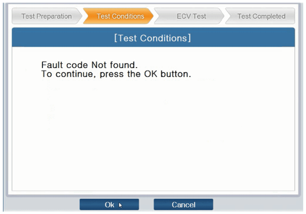
| 3. |
Check if other DTC codes are found before inspecting ECV
compressor. If found, solve these problems first. Otherwise, press
''OK'' button to continue.
[ECV4]
|
| 4. |
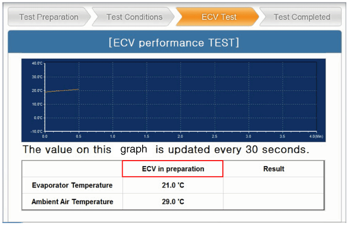
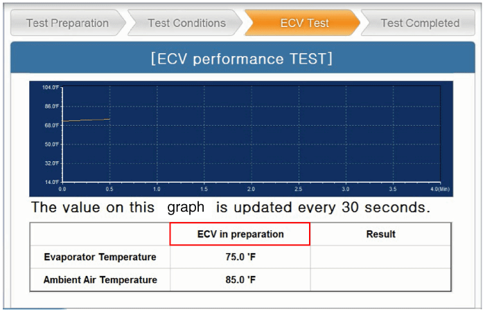
Start inspection
[ECV5]
[ECV6]
|

| 5. |
Check the result of inspection.
[ECV7]
[ECV8]
|
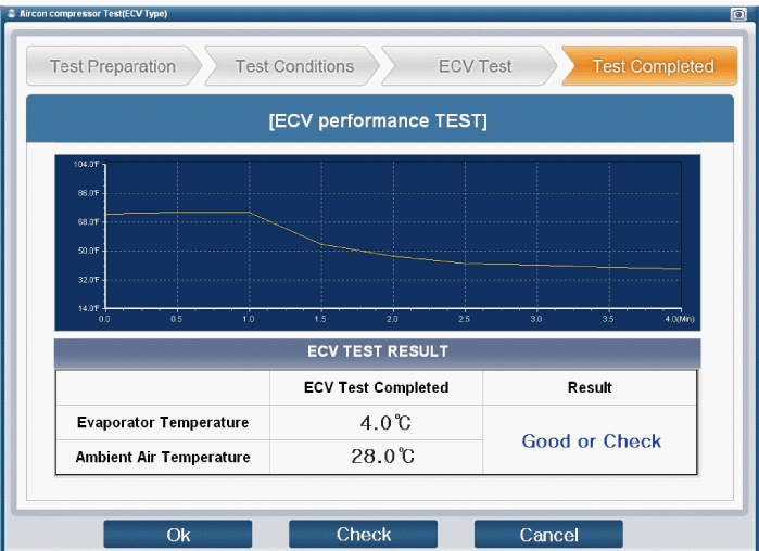

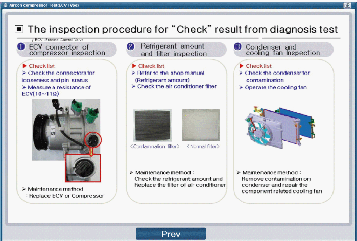
| 6. |
If the result shows "Check" , click "Check" and follow the instruction.
|
| 7. |
Inspect ECV again from the first step. |
| Disassembly |
| 1. |
Remove the front tire [RH]. |
| 2. |
Remove the engine room right side under cover (A) by loosening the mounting nuts.
|
| 3. |
Loosen the drive belt.
(Refer to Engine Mechanical System - " Drive Belt") |
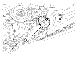
| 4. |
Remove the clutch bolt (A) while holding the pulley with a clutch bolt remover (09977-3R000).
|
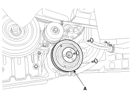
| 5. |
Loossen the limiter bolts and then remove the limiter & hub assembly (A).
|
| 6. |
Remove the pulley (B) after removing the snap ring (A) with a snap ring plier.
|
| 7. |
Reassemble in the reverse order of disassembly.
|
 Compressor Components and Components Location
Components
1. Clutch Bolt2. Limiter Bolt3. Limiter & Hub Assembly4. Snap Ring5. Pulley6. Compressor Assembly
...
 Condenser Components and Components Location
Components
1. Condenser
...
Other Information:
Rear Seat Assembly Repair procedures
Replacement
[Second row seat assembly]
[7Seat/8Seat]
1.
Loosen the second row seat front mounting bolts (A) after opening the cap (B).
2.
Pull up the seat by pulling the stand-up lever.
...
Intake Actuator Description and Operation
Description
The intake actuator is located at the blower unit. It
regulates the intake door by a signal from the control unit. Pressing
the intake selection switch will shift between recirculat ...
Categories
- Home
- First Generation
- Second Generation
- Third generation
- Kia Sedona YP 2014-2026 Owners Manual
- Kia Sedona YP 2014-2026 Service Manual

Copyright © www.kisedona.com 2016-2026