 Kia Sedona: Components and Components Location
Third generation YP (2014-2025) / Kia Sedona YP Service Manual / Engine Mechanical System / Cylinder Head Assembly / Components and Components Location
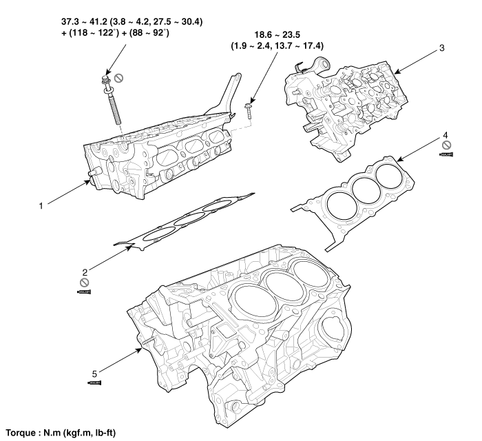
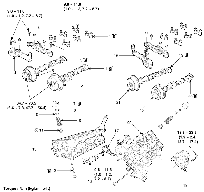
| Components |

| 1. RH Cylinder head 2. RH Cylinder head gasket 3. LH Cylinder head | 4. LH Cylinder head gasket 5. Cylinder block |

| 1. Camshaft bearing cap 2. Camshaft thrust bearing cap 3. RH Exhaust camshaft 4. RH Intake camshaft 5. RH Exhaust CVVT assembly 6. RH Intake CVVT assembly 7. Mechanical lash adjuster (MLA) 8. Retainer lock | 9. Retainer 10. Valve spring 11. Valve stem seal 12. Valve 13. RH Intake camshaft OCV 14. RH Exhaust camshaft OCV 15. RH Cylinder head 16. LH Exhaust camshaft OCV | 17. LH Intake camshaft OCV 18. Fuel pump bracket 19. LH Intake camshaft 20. LH Exhaust camshaft 21. LH Intake CVVT assembly 22. LH Intake CVVT assembly 23. LH Cylinder head |
 Valve Clearance Adjustment
Valve Clearance Inspection and Adjustment
Inspect and adjust the valve clearance when the engine is
cold (Engine coolant temperature : 20°C [68°F]) and cylinder hea ...
Other Information:
Camshaft Position Sensor (CMPS) Troubleshooting
Wave Form
...
Components and Components Location
Components Location
1. Front axle2. Front lower arm3. Drive shaft4. Sub frame5. Stabilizer bar6. Steering gearbox7. Stabilizer link8. Front strut assembly
...
Categories
- Home
- First Generation
- Second Generation
- Third generation
- Kia Sedona YP 2014-2025 Owners Manual
- Kia Sedona YP 2014-2025 Service Manual
Copyright © www.kisedona.com 2016-2025

