
 Kia Sedona: Components and Components Location
Third generation YP (2014-2026) / Kia Sedona YP Service Manual / Body Electrical System / Surround View Monitoring (SVM) System / Components and Components Location
| Components |
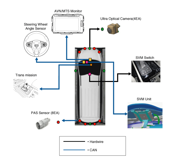
1) SVM unit basically uses C-CAN signal only to communicate about the vehicle''s condition.
2) Other unit''s B-CAN, P-CAN, and MM-CAN signals are changed to C-CAN signal and sent to SVM unit by CGW (Central Gate Way).
|

Component Functions
| No. | Components | Quantity | Major Role | ||||||
| 1 | SVM Unit | 1 |
| ||||||
| 2 | Ultra optical camera (190 degrees) | 4 |
| ||||||
| 3 | AVN Head Unit | 1 |
| ||||||
| 4 | SVM Switch | 1 |
|

 Description and Operation
Description
Surround View Monitoring System (SVM) is the system that
allows video monitoring of 360 degrees around the vehicle. The system
consists of 4 ultra optical cameras mounted around the ...
Other Information:
Manifold Absolute Pressure Sensor (MAPS) Repair procedures
Inspection
1.
Connect the GDS to the Data Link Connector (DLC).
2.
Measure the output voltage of the MAPS at idle and IG ON.
Pressure [kPa (kgf/cm², psi)]Output Voltage (V) [Ref=5V]20.0 (0 ...
Repair procedures
Removal
[Horn (Low pitch)]
1.
Remove the engine room under cover.
(Refer to Engine Mechanical System - "Engine Room Under Cover")
2.
Remove the mounting clip (A).
3.
Remove the low pitch ...
Categories
- Home
- First Generation
- Second Generation
- Third generation
- Kia Sedona YP 2014-2026 Owners Manual
- Kia Sedona YP 2014-2026 Service Manual

Copyright © www.kisedona.com 2016-2026