 Kia Sedona: Valve Body Description and Operation
Third generation YP (2014-2025) / Kia Sedona YP Service Manual / Automatic Transaxle System / Hydraulic System / Valve Body Description and Operation
| Description |
The components of the valve body
| • |
Regulator valve (hydraulic control) |
| • |
Redirection valves (change the direction of ATF flow) |
| • |
Shift valve (shifting control) |
| • |
Manual valve (manually shifting control). |
| • |
Solenoid valves (each valves control) |
| Operation |
Solenoid valve operation table
| | SS-A | SS-B | UD/B_VFS | OD/C_VFS | 35R/C_VFS | 26/B_VFS |
| N/H | N/H | N/H | N/L | |||
| N, P | ● | | ● | | ● | |
| 1 | Δ | | | Δ | ● | |
| 2 | | | | ● | ● | ● |
| 3 | | ● | | ● | | |
| 4 | | | | | ● | |
| 5 | | ● | ● | | | |
| 6 | | | ● | | ● | ● |
| R | ● | ● | ● | | | |
● : Connected status
Δ : Connected at vehicle speed above 8km/h
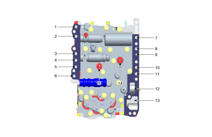
Valve Body Flow

| 1. To cooler 2. From cooler 3. Lubrication (rear) 4. OD clutch pressure 5. Reducing pressure (red2) 6. Reducing pressure (red1) 7. Damper release pressure 8. Damper apply pressure | 9. Lubrication (front) 10. 35R clutch pressure 11. 26 brake pressure 12. From oil pump 13. To oil pump 14. Underdrive brake pressure 15. Low & reverse pressure |
 Valve Body Components and Components Location
Components Location
1. Automatic transaxle2. Valve body assembly
Components
1. Pressure control valve (PCV) adjust screw2. Solenoid valve bracket3. Oil temperature sensor4. Line pressure co ...
 Valve Body Repair procedures
Removal
1.
Remove the under cover.
(Refer to Engine Mechanical System - "Engine Room Under Cover").
2.
Remove the ATF drain plug (A), allow the fluid to drain out and then reinstall the drain ...
Other Information:
Front Door Module Repair procedures
Replacement
1.
Remove the front door window glass.
(Refer to Front Door - "Front Door Window Glass")
2.
Remove the front door outside handle.
(Refer to Front Door - "Front Door Outside Hand ...
Certification label
The certification label is located on the driver's door sill at the center pillar.
This label shows the maximum allowable weight of the fully loaded vehicle. This
is called the GVWR (Gross Vehi ...
Categories
- Home
- First Generation
- Second Generation
- Third generation
- Kia Sedona YP 2014-2025 Owners Manual
- Kia Sedona YP 2014-2025 Service Manual
Copyright © www.kisedona.com 2016-2025
