 Kia Sedona: Transaxle Control Module (TCM) Schematic Diagrams
Third generation YP (2014-2026) / Kia Sedona YP Service Manual / Automatic Transaxle System / Automatic Transaxle Control System / Transaxle Control Module (TCM) Schematic Diagrams
TCM Connector
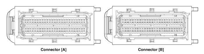
TCM terminal function
Connector [A]
| Pin | Description |
| 10 | CAN (High) |
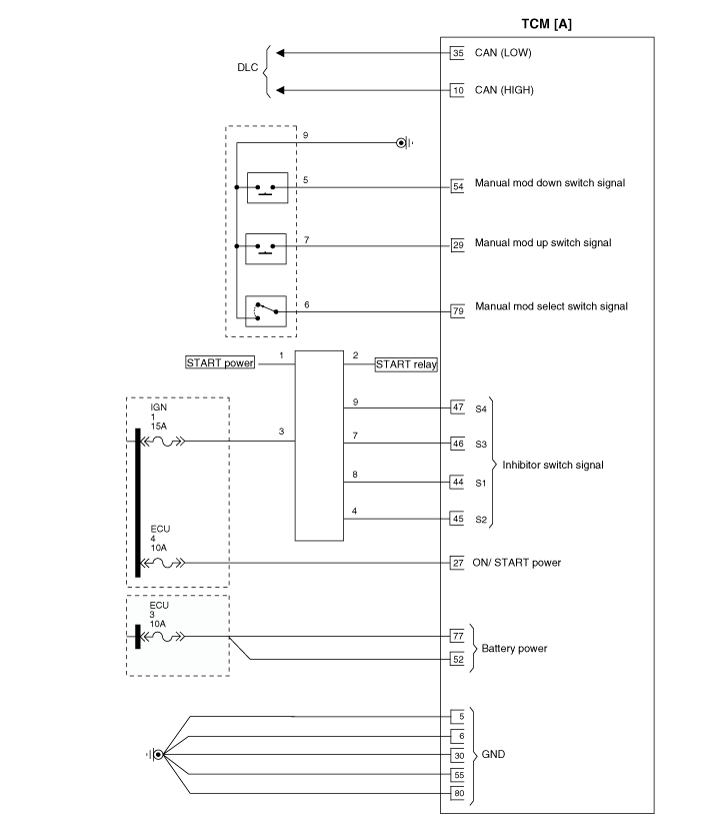
| 27 | Ignition switch |
| 29 | Sports mode up switch |
| 35 | CAN (Low) |
| 44 | Inhibitor switch signal ''S1'' |
| 45 | Inhibitor switch signal ''S2'' |
| 46 | Inhibitor switch signal ''S3'' |
| 47 | Inhibitor switch signal ''S4'' |
| 54 | Sports mode down switch |
| 79 | Sports mode Select switch |
| 85 | Reverse lamp relay |
| 86 | P/N relay |
Connector [B]
| Pin | Description |
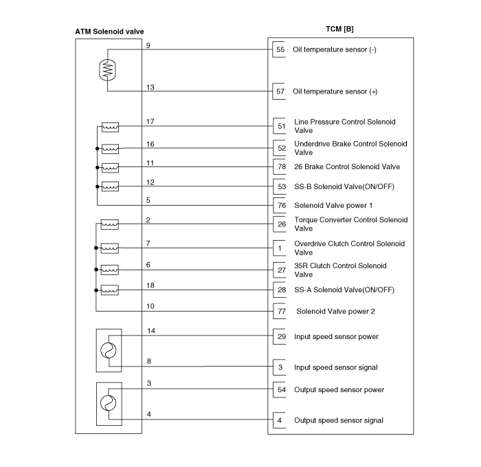
| 1 | Overdrive clutch control solenoid valve (VFS) |
| 3 | Input speed sensor signal |
| 4 | Output speed sensor signal |
| 26 | Torque converter control solenoid valve (VFS) |
| 27 | 35R Clutch control solenoid valve (VFS) |
| 28 | SS-A Solenoid valve (ON/OFF) |
| 29 | Input speed sensor power |
| 51 | Line pressure control solenoid valve (VFS) |
| 52 | Underdrive brake control solenoid valve (VFS) |
| 53 | SS-B Solenoid valve (ON/OFF) |
| 54 | Output speed sensor power |
| 55 | Oil temperature sensor (-) |
| 57 | Oil temperature sensor (+) |
| 76 | Solenoid valve power 1 |
| 77 | Solenoid valve power 2 |
| 78 | 26 Brake control solenoid valve (VFS) |
TCM Terminal input/ output signal
Connector [A]
| Pin No. | Signal | Condition | Type | Level |
| 29 | Sports mode up switch | Up ON | Input | 0V/Battery voltage level |
| Other | 9V < Battery voltage level < 16V | |||
| 44 | Inhibitor switch signal "S1" | ON | Input | 9V < Battery voltage level < 16V |
| OFF | 0V/Battery voltage level | |||
| 45 | Inhibitor switch signal "S2" | ON | Input | 9V < Battery voltage level < 16V |
| OFF | 0V/Battery voltage level | |||
| 46 | Inhibitor switch signal "S3" | ON | Input | 9V < Battery voltage level < 16V |
| OFF | 0V/Battery voltage level | |||
| 47 | Inhibitor switch signal "S4" | ON | Input | 9V < Battery voltage level < 16V |
| OFF | 0V/Battery voltage level | |||
| 54 | Sports mode down switch | Down ON | Input | 0V/Battery voltage level |
| Other | 9V < Battery voltage level < 16V | |||
| 79 | Sports mode select switch | Sport mode | Input | 0V/Battery voltage level |
| Other | 9V < Battery voltage level < 16V | |||
| 85 | Rear lamp relay | R ON | Output | 0V/Battery voltage level |
| Other | 9V < Battery voltage level < 16V | |||
| 86 | P/N relay | P-R change | Output | Min. Operation voltage: Battery voltage ≥ 6.0V |
| Max. Operation voltage: Battery voltage ≤ 16.0V | ||||
| P/N range position |
Connector [B]
| Pin No. | Signal | Condition | Type | Level |
| 1 | Overdrive clutch control solenoid valve | | Output | 0V/Battery voltage level |
| 9V < Battery voltage level < 16V | ||||
| Power supply : V_SOL1 | ||||
| 3 | Input speed sensor signal | High | Input | 0.7V/1.4V |
| Low | ||||
| 4 | Output speed sensor signal | High | Input | 0.7V/1.4V |
| Low | ||||
| 26 | Torque converter control solenoid valve | | Output | 0V/Battery voltage level |
| 9V < Battery voltage level < 16V | ||||
| 27 | 35R clutch control solenoid valve | | Output | 0V/Battery voltage level |
| 9V < Battery voltage level < 16V | ||||
| 28 | SS-A Solenoid valve (ON/OFF) | High | Output | 0V/Battery voltage level |
| Low | 9V < Battery voltage level < 16V | |||
| 29 | Input speed sensor power | ON | Power | 0V/7.5V |
| OFF | ||||
| 51 | Line pressure control solenoid valve | | Output | 0V/Battery voltage level |
| 9V < Battery voltage level < 16V | ||||
| 52 | Underdrive brake control solenoid valve | | Output | 0V/Battery voltage level |
| 9V < Battery voltage level < 16V | ||||
| Power supply : V_SOL2 | ||||
| 53 | SS-B Solenoid valve (ON/OFF) | High | Output | 0V/Battery voltage level |
| Low | 9V < Battery voltage level < 16V | |||
| 54 | Output speed sensor power | ON | Power | 0V/7.5V |
| OFF | ||||
| 55 | Oil temperature sensor (-) | | Ground | 0V |
| 76 | Solenoid valve power 1 | ON | Power | 0V/Battery voltage level |
| OFF | 9V < Battery voltage level < 16V | |||
| 77 | Solenoid valve power 1 | ON | Power | 0V/Battery voltage level |
| OFF | 9V < Battery voltage level < 16V | |||
| 78 | 26 brake control solenoid valve | | Output | 0V/Battery voltage level |
| 9V < Battery voltage level < 16V | ||||
| Power supply : V_SOL2 |
| Circuit Diagram |
 Transaxle Control Module (TCM) Description and Operation
Description
The module receives and processes signals from various
sensors and implements a wide range of transaxle controls to ensure
optimal driving conditions for the driver.
Functions
...
 Transaxle Control Module (TCM) Repair procedures
Inspection
1.
TCM ground circuit test: Measure resistance between TCM and
chassis ground using the backside of TCM harness connector as TCM side check point.
Specification: Below 1Ω
...
Other Information:
Rear Bumper Cover Repair procedures
Replacement
•
When prying with a flat-tip screwdriver, wrap it with
protective tape, and apply protective tape around the related parts, to
prevent damage. ...
Record your key number
The key code number is stamped on the bar code tag attached to the key set. Should
you lose your keys, this number will enable an authorized Kia dealer to duplicate
the keys easily. Remove the b ...
Categories
- Home
- First Generation
- Second Generation
- Third generation
- Kia Sedona YP 2014-2026 Owners Manual
- Kia Sedona YP 2014-2026 Service Manual

Copyright © www.kisedona.com 2016-2026