 Kia Sedona: Smart key Diagnostic Repair procedures
Third generation YP (2014-2026) / Kia Sedona YP Service Manual / Body Electrical System / Smart key System / Smart key Diagnostic Repair procedures
| Inspection |
Self Diagnosis With Scan Tool
Using the GDS, it can quickly diagnose defects of SMART KEY
system. GDS can operate actuator forcefully, monitor input/output values
and perform self diagnosis.
The following three features will be major problem in SMART KEY system.
| 1. |
Problem in SMART KEY unit input. |
| 2. |
Problem in SMART KEY unit. |
| 3. |
Problem in SMART KEY unit output. |
So, the following three diagnosis operations will be the major problem solution process.
| 1. |
SMART KEY unit Input problem : switch diagnosis |
| 2. |
SMART KEY unit problem : communication diagnosis |
| 3. |
SMART KEY unit Output problem : antenna and switch output diagnosis |
Switch Diagnosis
| 1. |
Connect the cable of GDS to the data link connector in driver side crash pad lower panel, turn the power on GDS. |
| 2. |
Select the vehicle model and then SMART KEY system. |
| 3. |
Select the "SMART KEY unit". |
| 4. |
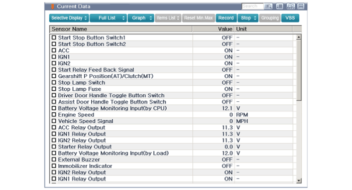
After IG ON, select the "Current data".
|
| 5. |
You can see the situation of each switch on scanner after connecting the "current data" process.
|
Communication Diagnosis With GDS (Self Diagnosis)
| 1. |
Communication diagnosis checks for normal operation in each component. |
| 2. |
Connect the cable of GDS to the data link connector in driver side crash pad lower panel. |
| 3. |
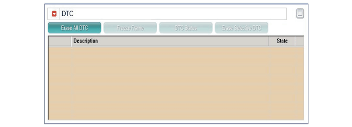
After IG ON, select the "DTC".
|
Antenna Actuation Diagnosis
| 1. |
Connect the cable of GDS to the data link connector in driver side crash pad lower panel. |
| 2. |
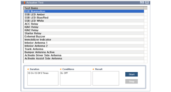
After IG ON, select the "Actuation Test".
|
| 3. |
Set the smart key near the corresponding antenna and operate it using GDS. |
| 4. |
If the LED of smart key is blinking, the smart key is normal. |
| 5. |
If the LED of smart key is not blinking, check the voltage of smart key battery. |
| 6. |
Antenna actuation
|
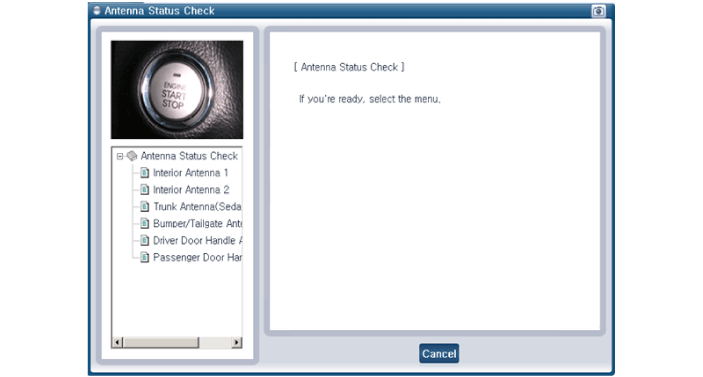
Antenna Status Check
| 1. |
Connect the cable of GDS to the data link connector in driver side crash pad lower panel. |
| 2. |
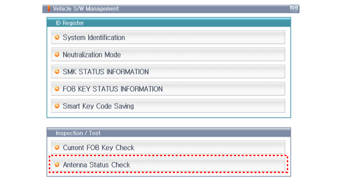
Select the "Antenna Status Check".
|
| 3. |
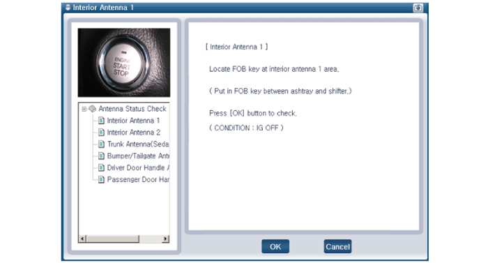
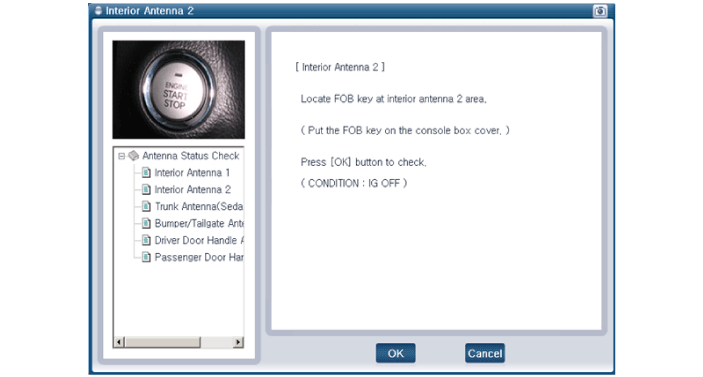
After IG ON, select the "Antenna Status Check".
|
| 4. |
Set the smart key near the corresponding antenna and operate it using GDS.
|
| 5. |
If the smart key operates normally, it means that the
corresponding antenna, smart key (transmission & reception) and
exterior receiver are also normal. |
| 6. |
Antenna status
|
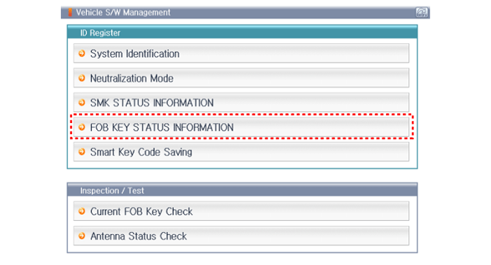
FOB Status Check
| 1. |
Connect the cable of GDS to the data link connector in driver side crash pad lower panel. |
| 2. |
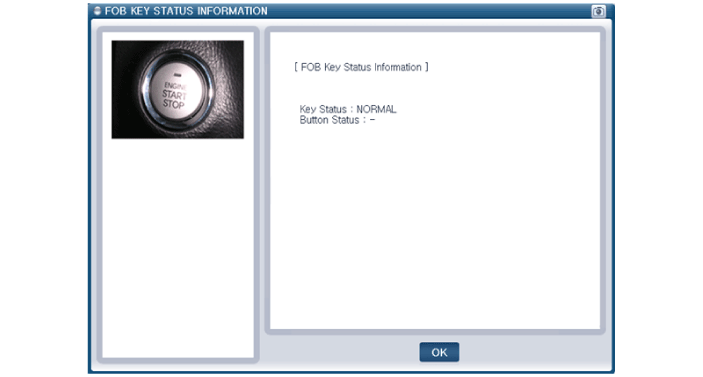
After IG ON, select the "FOB KEY STATUS INFO".
|
Smart Key Status Check
| 1. |
Connect the cable of GDS to the data link connector in driver side crash pad lower panel. |
| 2. |
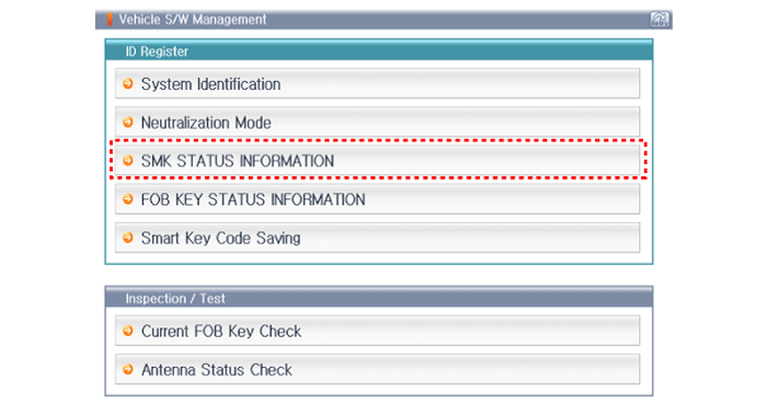
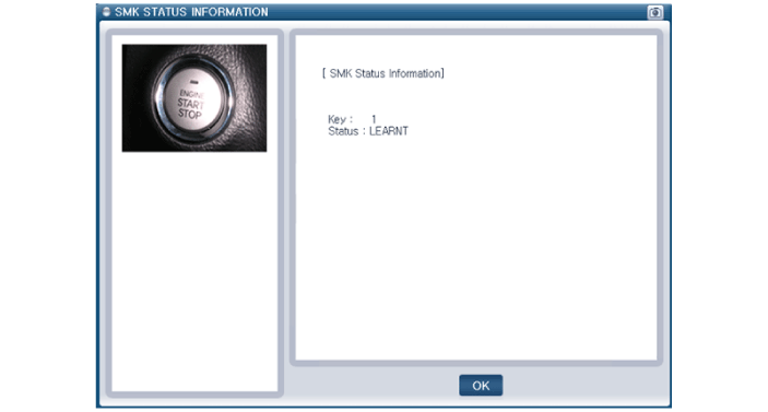
After IG ON, select the "SMK STATUS INFO".
|
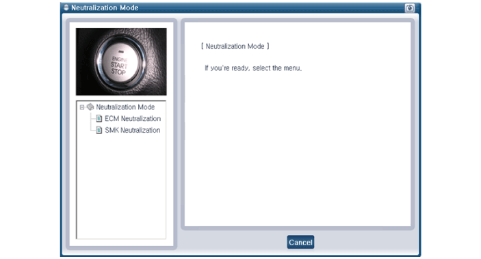
Neutralization Status Check
| 1. |
Connect the cable of GDS to the data link connector in driver side crash pad lower panel. |
| 2. |
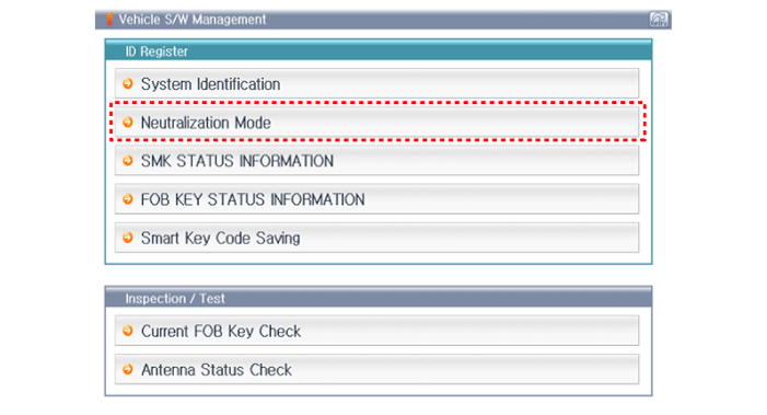
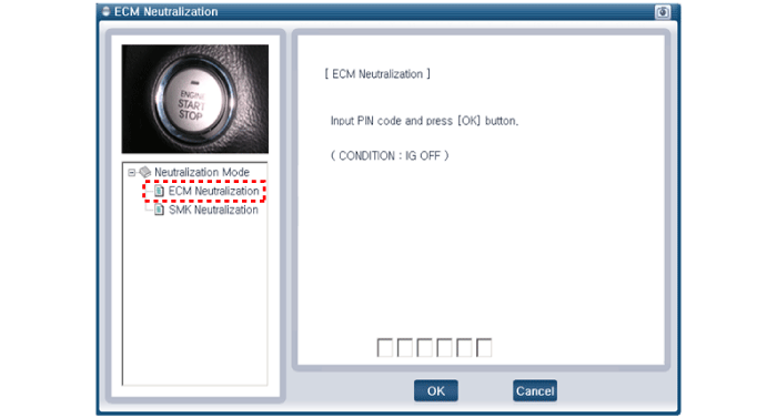
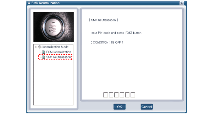
After IG ON, select the "Neutralization mode".
|
| 3. |
Select the "ECM Neutralization" or "SMK Neutralization".
|
 Description and Operation
Description
The SMART KEY system is a system that allows the user to
access and operate a vehicle in a very convenient way. To access the
vehicle, no traditional key or remote control unit is n ...
 Smart key Repair procedures
Smart Key
Smart Key Code Saving
1.
Connect the DLC cable of GDS to the data link connector (16
pins) in driver side crash pad lower panel, and then turn the power on
GDS.
2.
Select the ve ...
Other Information:
Storing positions into memory using the buttons on the door
Storing driver ...
Delivery Pipe Repair procedures
Removal
When removing the high pressure fuel pump, high pressure fuel
pipe, delivery pipe, and injector, injury may be caused by leakage of
high pressure fuel. For ...
Categories
- Home
- First Generation
- Second Generation
- Third generation
- Kia Sedona YP 2014-2026 Owners Manual
- Kia Sedona YP 2014-2026 Service Manual
Copyright © www.kisedona.com 2016-2026

