 Kia Sedona: Variable Intake Solenoid (VIS) Valve Repair procedures
Third generation YP (2014-2026) / Kia Sedona YP Service Manual / Engine Control / Fuel System / Engine Control System / Variable Intake Solenoid (VIS) Valve Repair procedures
| Inspection |
| 1. |
Turn the ignition switch OFF. |
| 2. |
Disconnect the VIS valve connector. |
| 3. |
Measure resistance between the VIS valve terminals 1 and 2. |
| 4. |
Check that the resistance is within the specification.
|
| Removal |
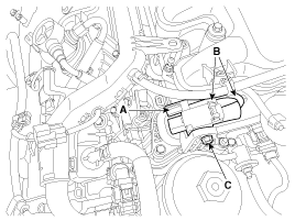
| [Valve 1] |
| 1. |
Turn the ignition switch OFF and disconnect the battery negative (-) terminal. |
| 2. |
Disconnect the variable intake solenoid valve connector (A). |
| 3. |
Disconnect the vacuum hoses (B) from the valve. |
| 4. |
Remove the mounting nut (C), and then remove the valve from surge tank.
|
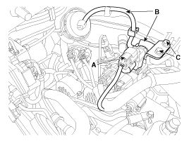
| [Valve 2] |
| 1. |
Turn the ignition switch OFF and disconnect the battery negative (-) terminal. |
| 2. |
Disconnect the variable intake solenoid valve connector (A). |
| 3. |
Disconnect the vacuum hoses (B) from the valve. |
| 4. |
Remove the mounting nut (C), and then remove the valve from surge tank.
|
| Installation |
|
| 1. |
Install in the reverse order of removal.
|
 Variable Intake Solenoid (VIS) Valve Schematic Diagrams
Circuit Diagram
...
 Fuel Pressure Control Valve (FPCV) Specifications
Specification
ItemSpecificationCoil Resistance (Ω)1.04 ~ 1.27 [23°C(73.4°F)]
...
Other Information:
High Beam Indicator Light
This indicator light illuminates :
When the headlights are on and in the high beam position
When the turn signal lever is pulled into the Flash-to-Pass position.
...
Repair procedures
Inspection
1.
After disconnecting the vapor hose from the PCV valve, remove the PCV valve.
2.
Reconnect the PCV valve to the vapor hose.
3.
Inspect the PCV valve operation.
(1)
Run the ...
Categories
- Home
- First Generation
- Second Generation
- Third generation
- Kia Sedona YP 2014-2026 Owners Manual
- Kia Sedona YP 2014-2026 Service Manual
Copyright © www.kisedona.com 2016-2026


