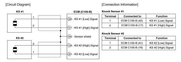
 Kia Sedona: Knock Sensor (KS) Schematic Diagrams
Third generation YP (2014-2026) / Kia Sedona YP Service Manual / Engine Control / Fuel System / Engine Control System / Knock Sensor (KS) Schematic Diagrams
| Circuit Diagram |

 Knock Sensor (KS) Description and Operation
Description
Knocking is a phenomenon characterized by undesirable
vibration and noise that can cause engine damage. Two Knock Sensors (KS)
are installed inside the V-valley of the cylinder bloc ...
 Knock Sensor (KS) Repair procedures
Removal
[Bank 1]
1.
Turn the ignition switch OFF and disconnect the battery negative (-) terminal.
2.
Remove the intake manifold.
(Refer to Engine Mechanical System - "Intake Manifold")
...
Other Information:
Tire sidewall labeling
This information identifies and describes the fundamental characteristics of
the tire and also provides the tire identification number (TIN) for safety standard
certification. The TIN can be use ...
Steering Gear box Repair procedures
Removal
1.
Remove the front wheel and tire (A) from front hub.
Tightening torque :
88.2 ~ 107.8 N.m (9.0 ~ 11.0 kgf.m, 65.0 ~ 79.5 lb-ft)
•
Be careful ...
Categories
- Home
- First Generation
- Second Generation
- Third generation
- Kia Sedona YP 2014-2026 Owners Manual
- Kia Sedona YP 2014-2026 Service Manual
Copyright © www.kisedona.com 2016-2026
