Kia Sedona: Steering Gear box Repair procedures - Electric Power Steering - Steering System - Kia Sedona YP Service ManualKia Sedona: Steering Gear box Repair procedures

Third generation YP (2014-2024) / Kia Sedona YP Service Manual / Steering System / Electric Power Steering / Steering Gear box Repair procedures

Removal
1.
Remove the front wheel and tire (A) from front hub.

Tightening torque :
88.2 ~ 107.8 N.m (9.0 ~ 11.0 kgf.m, 65.0 ~ 79.5 lb-ft)

   
•
Be careful not to damage the hub bolts when removing the front wheel and tire (A).
2.
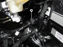
Disconnect the connector (A).

3.
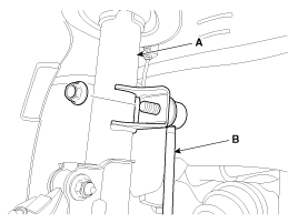
Disconnect the stabilizer link(B) with the front strut assembly(A) after loosening the nut.

Tightening torque :
98.1 ~ 117.7N.m (10.0 ~ 12.0kgf.m, 72.3 ~ 86.8lb-ft)

4.
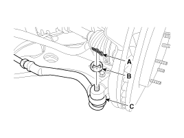
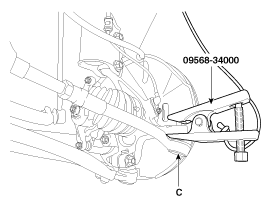
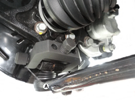
Remove the tie rod end ball joint (C) from the knuckle by using the SST (09568-34000).
(1)
Remove the split pin (A).
(2)
Remove the castle nut (B).
(3)
Use the SST (09568-34000).

Tightening torque :
23.5 ~ 33.3N.m (2.4 ~ 3.4kgf.m, 19.4 ~ 24.6lb-ft)

   
•
When using SST, be sure not to damage the dust cover of lower arm ball joint.
•
Keep the SST tied to the car as there is a risk of injury when the SST is dropped whilst removing the lower arm ball joint.
•
Be sure to use the SST as the peripheral parts may get damaged from attempts to remove the lower arm ball joint using general tools such as lever.
5.
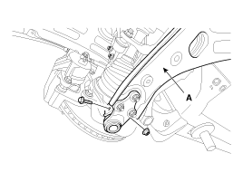
Loosen the bolt & nut and then remove the lower arm (A).

Tightening torque :
98.1 ~ 117.7N.m (10.0 ~ 12.0kgf.m, 72.3 ~ 86.8lb-ft)

6.
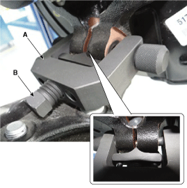
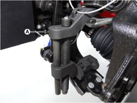
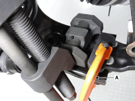
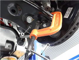
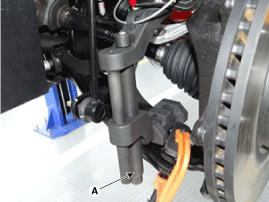
Remove the front lower arm from the front knuckle using the SST (0K545-A9100).
(1)
After removing bolts from the front knuckle, install and tighten the sub body bolt (A) .

(2)
Input the sub body (A) between the front knuckle and the sub body bolt.
(3)
Tighten bolt (B) of the sub body bolt to broaden the gap of the front knuckle.

(4)
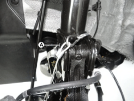
Install the safe wire (A).

   
Install a safe wire on the front strut to prevent dropping the SST and hurting technicians.
(5)
Install the main body, between the front strut and the lower arm.

(6)
To avoid the main body coming off, install a fixing clamp (A) beside the main body.

(7)
After installing a fixing clamp, rotate the handle (B) clock wise till the clamp is fixed on a lower arm.

(8)
Tighten a main body bolt (A) of the slowly and remove the lower arm from the front knuckle.

7.
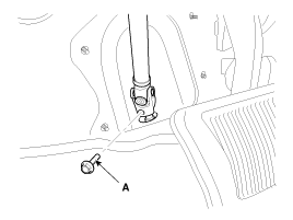
Loosen the bolt (A) and then disconnect the universal joint assembly from the pinion of the steering gear box.

Tightening torque :
32.4 ~ 37.3N.m (3.3 ~ 3.8kgf.m, 23.9 ~ 27.5lb-ft)

   
•
Keep the gear in neutral-range to prevent damaging the clock spring inner cable when handling the steering wheel.
•
Do not reuse the bolt.

8.
Remove the under cover.
(Refer to Engine Mechanical System - "Engine Room Under Cover")
9.
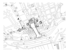
Remove the roll rod stopper bolt (A).

Tightening torque :
107.9 ~ 127.5N.m (11.0 ~ 13.0kgf.m, 79.6 ~ 94.0lb-ft)

10.
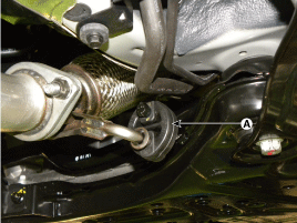
Disconnect the muffler rubber hanger (A).

11.
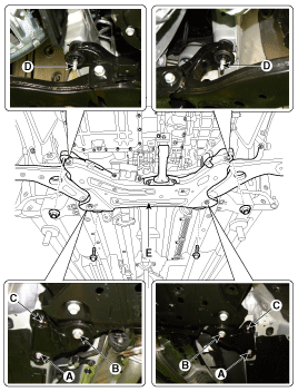
Loosen the bolts & nuts and then remove the sub frame.

Tightening torque :
Bolts :
(A) 44.1 ~ 58.8N.m (4.5 ~ 6.0kgf.m, 32.5 ~ 43.4lb-ft)
(B) 156.9 ~ 176.5N.m (16.0 ~ 18.0kgf.m, 115.7 ~ 130.2lb-ft)
Nuts :
(C) 44.1 ~ 58.8N.m (4.5 ~ 6.0kgf.m, 32.5 ~ 43.4lb-ft)
(D) 156.9 ~ 176.5N.m (16.0 ~ 18.0kgf.m, 115.7 ~ 130.2lb-ft)

12.
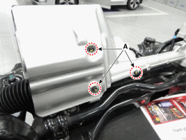
Loosen 3 bolts (A) and then remove the protector.

Tightening torque :
6.9 ~ 10.8 N.m(0.7 ~ 1.1 kgf.m, 5.1 ~ 8.0 lb-ft)

13.
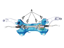
Remove the steering gearbox from the cross member by loosening 4 mounting bolts (A).

Tightening torque :
88.2 ~ 107.8 N.m (9.0 ~ 11.0 kgf.m, 65.0 ~ 79.5 lb-ft)

14.
Install in the reverse order of removal.
15.
Check the wheel Alignment.
(Refer to Suspension System - "Alignment")
Steering Column and Shaft Repair procedures
Removal 1. Disconnect the battery negative cable from the battery and then wait for at least 30 seconds. 2. Turn the steering wheel so that the front wheels can face straight ahead. 3. Rem ...

Hydraulic Power Steering System
...

Other Information:

Rear Center Seat Belt Retractor Repair procedures
Replacement [Second row center seat belt retractor]     When installing the belt, make sure not to damage the retractor. 1. Remove the roof trim assembly. (Refer t ...

Auto Head lamp leveling Unit Schematic Diagrams
Circuit Diagram ...

Categories


Copyright © www.kisedona.com 2016-2024