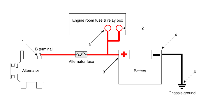
Check that the battery cables are connected to the correct terminals.
•
Disconnect the battery cables when the battery is given a quick charge.
•
Never disconnect the battery while the engine is running.
•
Inspect the battery test using the load tester and battery tester.
Battery Voltage Inspection
1.
After having driven the vehicle and in the case that 20
minutes have not passed after having stopped the engine, turn the
ignition switch ON and turn on the electrical system (headlamp, blower
motor, rear defogger etc.) for 60 seconds to remove the surface charge.
2.
Turn the ignition switch OFF and turn off the electrical systems.
3.
Measure the battery voltage between the negative (-) and positive (+) terminals of the battery.
Standard voltage : About 12.5 ~ 12.9V (20°C)
If the voltage is less than specification, charge the battery.
Charging Voltage Inspection
1.
Start the engine.
2.
Turn ON the electrical systems.
3.
Keep the engine speed at 2,500 rpm.
4.
Measure the battery voltage between the negative (-) and positive (+) terminals of the battery.
Standard voltage : About 13.5 ~ 14.5 V (20°C)
If the voltage is less than specification, charge the battery.
General Inspection
1.
Check that the battery terminals are not loose or corroded.
(Refer to Charging System - "Battery")
2.
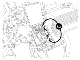
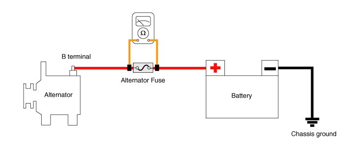
Check the fuses for continuity.
(1)
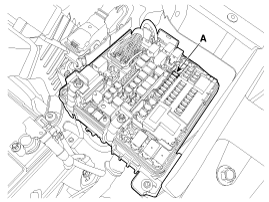
Check the alternator fuse for continuity.
(2)
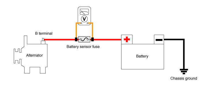
Measure the voltage as shown in the image below.
Standard value : Approximately 0 V
(3)
If the alternator fuse is blown, replace it as in the procedure below:
a.
Turn ignition switch OFF and disconnect the battery negative (-) terminal.
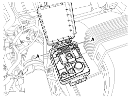
b.
Remove the battery positive (+) cable mounting nuts (A).
c.
Remove the battery positive (+) cable (B).
d.
Replace the norminal alternator fuse or battery cable.
e.
Install in the reverse order of removal.
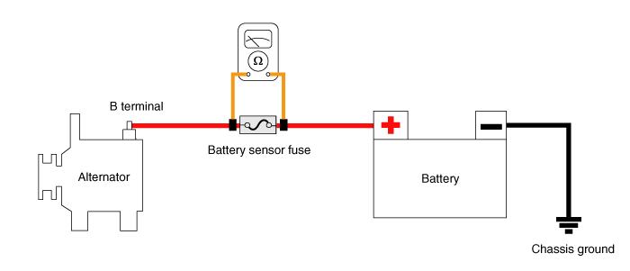
(1)
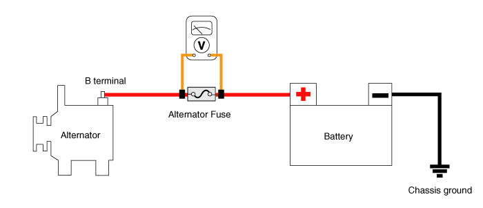
Check the battery sensor fuse for continuity (A).
(2)
If the alternator fuse is blown, replace the battery sensor fuse.
(3)
Measure the voltage as shown in the image below.
Standard value : Approximately 0 V
3.
Inspect Drive Belt
(1)
Visually check the belt for excessive wear, frayed cords etc.
If any defect has been found, replace the drive belt.
•
Cracks on the rib side of a belt are considered acceptable. If the belt has chunks missing from the ribs, it should be replaced.
4.
Measure and adjust drive belt tension.
(Refer to Engine Mechanical System - "Drive Belt")
5.
Visually check alternator wiring and listen for abnormal noises.
(1)
Check that the wiring is in good condition.
(2)
Check that there is no abnormal noise from the alternator while the engine is running.
6.
Check Discharge Warning Light Circuit
(1)
Warm up the engine and then turn it off.
(2)
Turn off all accessories.
(3)
Turn the ignition switch "ON". Check that the discharge warning light is lit.
(4)
Start the engine. Check that the light is lit.
If the light does not go off as specified, troubleshoot the discharge light circuit.
Terminal Tightening State Inspection
•
Alternator B+ terminal state
•
Alternator B+ termina tightening nut
•
Battery positive (+) terminal state
•
Battery positive (+) terminal tightening nut state
•
Battery negative (-) terminal state
•
Battery negative (-) terminal tightening nut state
•
Battery negative (-) terminal mounting bolt tightening state (Chassis ground)
•
Battery sensor negative (-) terminal state (With battery sensor)
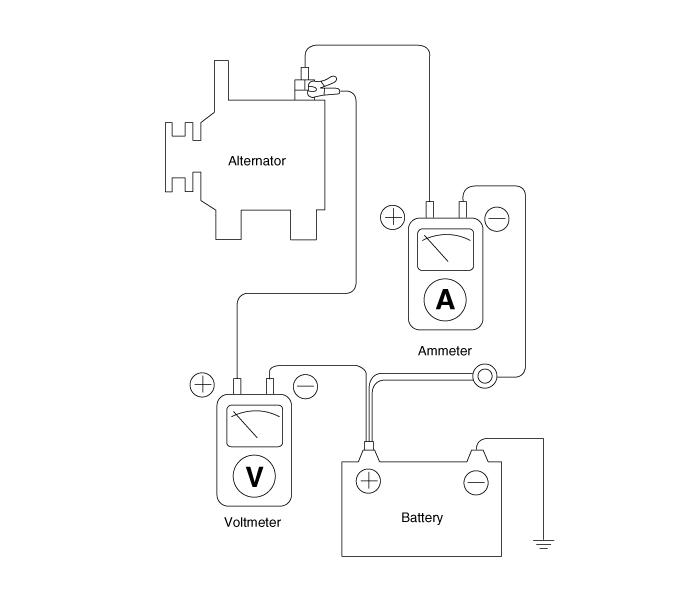
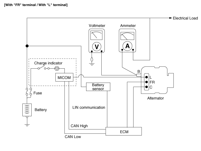
Electrical Specified Value Inspection (Using the Voltmeter and Ammeter)
1.
Voltage Drop Test of Alternator Output Wire
This test determines whether or not the wiring between the
alternator "B" terminal and the battery (+) terminal is good by the
voltage drop method.
(1)
Preparation
a.
Turn the ignition switch to "OFF".
b.
Disconnect the output wire from the alternator "B" terminal.
Connect the (+) lead wire of ammeter to the "B" terminal of alternator
and the (-) lead wire of ammeter to the output wire. Connect the (+)
lead wire of voltmeter to the "B" terminal of alternator and the (-)
lead wire of voltmeter to the (+) terminal of battery.
(2)
Test
a.
Start the engine.
b.
Turn on the headlamps and blower motor, adjust the engine speed until the ammeter indicates 20A and read the voltmeter.
(3)
Result
a.
The voltmeter may indicate the standard value.
Standard value : 0.2V max
b.
If the value of the voltmeter is higher than expected (above
0.2V max.), poor wiring is suspected. In this case check the wiring from
the alternator "B" terminal to the battery (+) terminal. Check for
loose connections, color change due to an over-heated harness, etc.
Correct them before testing again.
c.
Upon completion of the test, set the engine speed at idle.Turn off the headlamps, blower motor and the ignition switch.
2.
Output Current Test
This test determines whether or not the alternator gives an output current that is equivalent to the normal output.
(1)
Preparation
a.
Prior to the test, check the following items and correct as necessary.
Check the battery installed in the vehicle to ensure that it
is in good condition. Refer to the "Battery" section for checking
battery.
The battery used to test the output current should be partially discharged.
With a fully charged battery, the test may not be conducted correctly due to an insufficient load.
Check the tension of the alternator drive belt. Refer to the "Inspect drive belt" section for checking the belt tension.
b.
Turn off the ignition switch.
c.
Disconnect the battery ground cable.
d.
Disconnect the alternator output wire from the alternator "B" terminal.
e.
Connect a DC ammeter (0 to 150A) in series between the "B"
terminal and the disconnected output wire. Be sure to connect the (-)
lead wire of the ammeter to the disconnected output wire.
Tighten each connection securely, as a heavy current will flow. Do not rely on clips.
f.
Connect a voltmeter (0 to 20V) between the "B" terminal and
ground. Connect the (+) lead wire to the alternator "B" terminal and (-)
lead wire to a good ground.
g.
Connect the battery ground cable.
h.
Leave the engine hood open.
(2)
Test
a.
Check to see that the voltmeter reads the same value as the
battery voltage. If the voltmeter reads 0V, open circuit in the wire
between alternator "B" terminal and battery (+) terminal or poor
grounding is suspected.
b.
Start the engine and turn on the headlamps.
c.
Set the headlamps to high beam and the heater blower switch
to HIGH, quickly increase the engine speed to 2,500 rpm and read the
maximum output current value indicated by the ammeter.
•
After the engine start up, the charging current quickly
drops. Therefore, the above operation must be done quickly to read the
maximum current value correctly.
(3)
Result
a.
The ammeter reading must be higher than the limit value. If
it is lower despite the alternator output wire is in good condition,
remove the alternator from the vehicle and test it.
Limit value : 60% of the voltage rate
• The nominal output current value is shown on the nameplate affixed to the alternator body.
•
The output current value changes with the electrical load and
the temperature of the alternator itself. Therefore, the nominal output
current may not be obtained. If such is the case, keep the headlamps on
to discharge the battery or use lights of other vehicles to increase
the electrical load.
The nominal output current may not be obtained if the
temperature of the alternator itself or ambient temperature is too high.
In such a case, reduce the temperature before testing again.
b.
Upon completion of the output current test, lower the engine speed to idle and turn off the ignition switch.
c.
Disconnect the battery negative (-) terminal.
d.
Remove the ammeter and voltmeter and the engine tachometer.
e.
Connect the alternator output wire to the alternator "B" terminal.
f.
Connect the battery negative (-) terminal.
3.
Regulated Voltage Test
The purpose of this test is to check that the electronic voltage regulator controls voltage correctly.
(1)
Preparation
a.
Prior to the test, check the following items and correct if necessary.
Check that the battery installed on the vehicle is fully charged. Refer to the "Battery" section for checking the battery.
Check the alternator drive belt tension. Refer to the "Inspect drive belt" section for checking the belt tension.
b.
Turn ignition switch to "OFF".
c.
Disconnect the battery negative (-) terminal.
d.
Connect a digital voltmeter between the "B" terminal of the
alternator and ground. Connect the (+) lead of the voltmeter to the "B"
terminal of the alternator. Connect the (-) lead to good ground or the
battery (-) terminal.
e.
Disconnect the alternator output wire from the alternator "B" terminal.
f.
Connect a DC ammeter (0 to 150A) in series between the "B"
terminal and the disconnected output wire. Connect the (-) leadwire of
the ammeter to the disconnected output wire.
g.
Connect the battery negative (-) terminal.
(2)
Test
a.
Turn on the ignition switch and check to see that the voltmeter indicates the following value.
Voltage : Battery voltage
If it reads 0V, there is an open circuit in the wire between
the alternator "B" terminal and the battery and the battery (-)
terminal.
b.
Start the engine. Keep all lights and accessories off.
c.
Run the engine at a speed of about 2,500 rpm and read the voltmeter when the alternator output current drops to 10A or less
(3)
Result
a.
If the voltmeter reading doesn''t agree with the standard value, the voltage regulator or the alternator is faulty.
Regulated Voltage : 11.7 ~ 15.3V
b.
If the voltmeter reading doesn''t agree with the standard value, the voltage regulator or the alternator is faulty.
c.
Disconnect the battery negative (-) terminal.
d.
Remove the voltmeter and ammeter.
e.
Connect the alternator output wire to the alternator "B" terminal.
f.
Connect the battery negative (-) terminal.
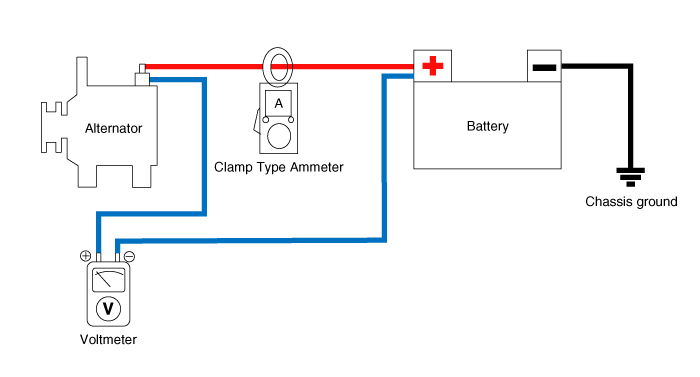
Electrical Specified Value Inspection (Using the Voltmeter and Clamp type Ammeter)
1.
Voltage Drop Test of Alternator Output Wire
This test determines whether or not the wiring between the
alternator "B" terminal and the battery (+) terminal is good by the
voltage drop method.
(1)
Preparation
a.
Turn the ignition switch to "OFF".
b.
Install the clamp type ammeter between battery positive (+) and alternator "B" terminal.
c.
Connect the (+) lead wire of voltmeter to the "B" terminal of
alternator and the (-) lead wire of voltmeter to the (+) terminal of
battery.
(2)
Test
a.
Start the engine.
b.
Turn on the headlamps and blower motor, adjust the engine speed until the ammeter indicates 20A and read the voltmeter.
(3)
Result
a.
The voltmeter may indicate the standard value.
Standard value : 0.2V max
b.
If the value of the voltmeter is higher than expected (above
0.2V max.), poor wiring is suspected. In this case check the wiring from
the alternator "B" terminal to the battery (+) terminal. Check for
loose connections, color change due to an over-heated harness, etc.
Correct them before testing again.
c.
Upon completion of the test, set the engine speed at idle.Turn off the headlamps, blower motor and the ignition switch.
2.
Output Current Test
This test determines whether or not the alternator gives an output current that is equivalent to the normal output.
(1)
Preparation
a.
Prior to the test, check the following items and correct as necessary.
Check the battery installed in the vehicle to ensure that it
is good condition. Refer to the "Battery" section for checking the
battery.
The battery used to test the output current should be partially discharged.
With a fully charged battery, the test may not be conducted correctly due to an insufficient load.
Check the tension of the alternator drive belt. Refer to the "Inspect drive belt" section for checking the belt tension.
b.
Turn off the ignition switch.
c.
Disconnect the battery negative (-) terminal.
d.
Install the clamp type ammeter between battery positive (+) and alternator "B" terminal.
e.
Connect a DC ammeter (0 to 150A) in series between the "B"
terminal and the disconnected output wire. Be sure to connect the (-)
lead wire of the ammeter to the disconnected output wire.
Tighten each connection securely, as a heavy current will flow. Do not rely on clips.
f.
Connect a voltmeter (0 to 20V) between the "B" terminal and
ground. Connect the (+) lead wire to the alternator "B" terminal and (-)
lead wire to a good ground.
g.
Connect the battery negative (-) terminal.
h.
Leave the engine hood open.
(2)
Test
a.
Check to see that the voltmeter reads the same value as the
battery voltage. If the voltmeter reads 0V, open circuit in the wire
between alternator "B" terminal and battery (+) terminal or poor
grounding is suspected.
b.
Start the engine and turn on the headlamps.
c.
Set the headlamps to high beam and the heater blower switch
to HIGH, quickly increase the engine speed to 2,500 rpm and read the
maximum output current value indicated by the ammeter.
•
After the engine start up, the charging current quickly
drops. Therefore, the above operation must be done quickly to read the
maximum current value correctly.
(3)
Result
a.
The ammeter reading must be higher than the limit value. If
it is lower despite the alternator output wire is in good condition,
remove the alternator from the vehicle and test it.
Limit value : 60% of the voltage rate
• The nominal output current value is shown on the nameplate affixed to the alternator body.
•
The output current value changes with the electrical load and
the temperature of the alternator itself. Therefore, the nominal output
current may not be obtained. If such is the case, keep the headlamps on
to discharge the battery or use lights of other vehicles to increase
the electrical load.
The nominal output current may not be obtained if the
temperature of the alternator itself or ambient temperature is too high.
In such a case, reduce the temperature before testing again.
b.
Upon completion of the output current test, lower the engine speed to idle and turn off the ignition switch
c.
Disconnect the battery negative (-) terminal.
d.
Remove the ammeter and voltmeter and the engine tachometer.
e.
Connect the alternator output wire to the alternator "B" terminal.
f.
Connect the battery negative (-) terminal.
3.
Regulated Voltage Test
The purpose of this test is to check that the electronic voltage regulator controls voltage correctly.
(1)
Preparation
a.
Prior to the test, check the following items and correct if necessary.
Check that the battery installed on the vehicle is fully charged. Refer to the "Battery" section for checking the battery.
Check the alternator drive belt tension. Refer to the "Inspect drive belt" section for checking the belt tension.
b.
Turn ignition switch to "OFF".
c.
Disconnect the battery negative (-) terminal.
d.
Connect a digital voltmeter between the "B" terminal of the
alternator and ground. Connect the (+) lead of the voltmeter to the "B"
terminal of the alternator. Connect the (-) lead to good ground or the
battery (-) terminal.
e.
Disconnect the alternator output wire from the alternator "B" terminal.
f.
Connect a DC ammeter (0 to 150A) in series between the "B"
terminal and the disconnected output wire.Connect the (-) lead wire of
the ammeter to the disconnected output wire.
g.
Connect the battery negative (-) terminal.
(2)
Test
a.
Turn on the ignition switch and check to see that the voltmeter indicates the following value.
Voltage : Battery voltage
If it reads 0V, there is an open circuit in the wire between
the alternator "B" terminal and the battery and the battery (-)
terminal.
b.
Start the engine. Keep all lights and accessories off.
c.
Run the engine at a speed of about 2,500 rpm and read the voltmeter when the alternator output current drops to 10A or less
(3)
Result
a.
If the voltmeter reading does not agree with the standard value, the voltage regulator or the alternator is faulty.
Regulated Voltage : 11.7 ~ 15.3V
b.
If the voltmeter reading does not agree with the standard value, the voltage regulator or the alternator is faulty.
c.
Disconnect the battery negative (-) terminal.
d.
Remove the voltmeter and ammeter.
e.
Connect the alternator output wire to the alternator "B" terminal.
f.
Connect the battery negative (-) terminal.
Vehicle parasitic current inspection
[Using the Ammeter]
1.
Turn the all electric devices OFF, and then turn the ignition switch OFF.
2.
Close all doors except the engine hood, and then lock all doors.
(1)
Disconnect the hood switch connector.
(2)
Close the trunk lid.
(3)
Close the doors or remove the door switches.
3.
Wait for a few minutes until the vehicle’s electrical systems go to sleep mode.
•
For an accurate measurement of a vehicle parasitic current,
all electrical systems should go to sleep mode. (It takes at least one
hour or at most one day.) However, an approximate vehicle parasitic
current can be measured after 10~20 minutes.
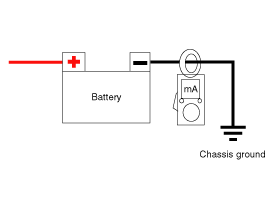
4.
Connect an ammeter in series between the battery (-) terminal
and the ground cable, and then disconnect the clamp from the battery
(-) terminal slowly.
•
Be careful that the lead wires of an ammeter do not come off
from the battery (-) terminal and the ground cable to prevent the
battery from being reset. In case the battery is reset, connect the
battery cable again, and then start the engine or turn the ignition
switch ON for more than 10 sec. Repeat the procedure from No. 1.
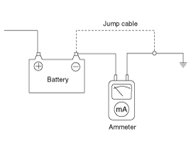
To prevent the battery from being reset during the inspection:
1)
Connect a jump cable between the battery (-) terminal and the ground cable.
2)
Disconnect the ground cable from the battery (-) terminal.
3)
Connect an ammeter between the battery (-) terminal and the ground cable.
4)
After disconnecting the jump cable, read the current value of the ammeter.
5.
Read the current value of the ammeter.
•
If the parasitic current is over the limit value, search for
abnormal circuit by removing the fuses one by one and checking for
parasitic current.
•
Reconnect only the fuse suspected of parasitic current and
search for the trouble unit by removing the components connected to the
circuit one by one until the parasitic draw drops below limit value.
Limit value (after 10~20 min.) : Below 50mA
[Using the Clamp type Ammeter]
1.
Turn the all electric devices OFF, and then turn the ignition switch OFF.
2.
Close all doors except the engine hood, and then lock all doors.
(1)
Disconnect the hood switch connector.
(2)
Close the trunk lid.
(3)
Close the doors or remove the door switches.
3.
Wait for a few minutes until the vehicle’s electrical systems go to sleep mode.
•
For an accurate measurement of a vehicle parasitic current,
all electrical systems should go to sleep mode. (It takes at least one
hour or at most one day.) However, an approximate vehicle parasitic
current can be measured after 10~20 minutes.
4.
Install the clamp type ammerter on battery negative (-) terminal.
5.
Read the current value of the ammeter.
•
If the parasitic current is over the limit value, search for
abnormal circuit by removing the fuses one by one and checking for
parasitic current.
•
Reconnect only the fuse suspected of parasitic current and
search for the trouble unit by removing the components connected to the
circuit one by one until the parasitic draw drops below limit value.
Specification
ItemSpecificationRated voltage13.5V , 150ASpeed in use1,500 ~ 18,000rpmVoltage regulatorIC Regulator built in typeDefault regulated voltage (V) [COM terminal]14.0 ~ 15.5 (-35°C)14. ...
Other Information:
Components and Components Location
Components
1. Front seat center side cover [LH]2. Front seat cushion vent mat [LH]3. Front seat cushion pad assembly [LH]4. Front seat cushion cover assembly [LH]5. Front seat cushion frame assem ...
Curtain Airbag (CAB) Module Description and Operation
Description
Curtain airbags are installed inside the headliner (LH and
RH) to protect the driver and passenger from danger when side crash
occurs. The SRSCM determines deployment of curtain air ...
 Kia Sedona: Repair procedures


 Schematic Diagrams
 Alternator Specifications