 Kia Sedona: Mode Control Actuator Repair procedures
Third generation YP (2014-2026) / Kia Sedona YP Service Manual / Heating,Ventilation And Air Conditioning / Heater / Mode Control Actuator Repair procedures
| Inspection |
| 1. |
Turn the ignition switch OFF. |
| 2. |
Disconnect the mode control actuator connector. |
| 3. |
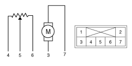
Verify that the mode control actuator operates to the defrost mode when 12V is connected to terminal 3 and ground to terminal 7.
Verify that the mode control actuator operates to the vent mode when connected in reverse.
|
| 4. |
Connect the mode control actuator connector. |
| 5. |
Turn the ignition switch ON. |
| 6. |
Check the voltage between terminals 5 and 4.
Specification
It will feedback the current position of the actuator to controls. |
| 7. |
If the measured voltage is not within the specification,
substitute with a verified temperature control actuator and check for
proper operation. |
| 8. |
Replace the mode control actuator if it is proved that there is a problem with it.
|
| Replacement |
| 1. |
Disconnect the negative (-) battery terminal. |
| 2. |
Remove the main crash pad assembly.
(Refer to Body - "Main Crash Pad Assembly") |
| 3. |
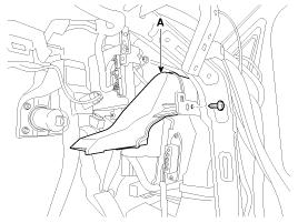
Remove the shower duct [LH] (A) after loosening the screw.
|
| 4. |
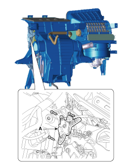
Disconnect the connector and then remove the mode control actuator (A) after loosening the mounting screws.
|
| 5. |
Install in the reverse order of removal. |
 Mode Control Actuator Description and Operation
Description
Located in the heater unit, the mode control actuator adjusts
the position of the mode door by operating the mode control actuator
according to the signal from the A/C control unit. ...
 Blower
...
Other Information:
Driving on grades
Reduce speed and shift to a lower gear before you start down a long or steep
downgrade. If you don ...
Injector Description and Operation
Description
Based on information from various sensors, the ECM can
calculate the fuel amount to be injected. The fuel injector is a
solenoid-operated valve and the fuel injection amount is cont ...
Categories
- Home
- First Generation
- Second Generation
- Third generation
- Kia Sedona YP 2014-2026 Owners Manual
- Kia Sedona YP 2014-2026 Service Manual
Copyright © www.kisedona.com 2016-2026


