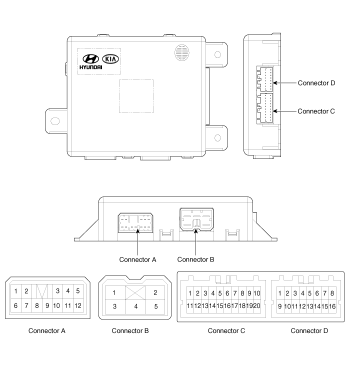
 Kia Sedona: IMS (Integrated Memory System) module Components and Components Location
Third generation YP (2014-2025) / Kia Sedona YP Service Manual / Body Electrical System / IMS (Integrated Memory) / IMS (Integrated Memory System) module Components and Components Location
| Components |

Connector Pin Information
| No. | Connecter A | Connecter B | Connecter C | Connecter D |
| 1 | - | Batt (+) | - | - |
| 2 | Front tilt motor (Up) | GND | - | Seat rear height sensor |
| 3 | Rear height motor (Up) | Batt (+) | Slide switch signal (Forward) | - |
| 4 | Reclining motor (Forward) | - | Reclining switch signal (Forward) | Body CAN (High) |
| 5 | Slide motor (Forward) | GND | Front tilt switch signal (Up) | Body CAN (Low) |
| 6 | - | | Rear height switch signal (Up) | - |
| 7 | Front tilt motor (Down) | Slide sensor | IGN1 | |
| 8 | - | Reclinin sensor | Batt (+) | |
| 9 | - | Front tilt sensor | GND | |
| 10 | Rear height motor (Down) | Seat position sensor power | - | |
| 11 | Reclining motor (Backward) | - | - | |
| 12 | Slide motor (Backward) | - | - | |
| 13 | | Slide switch signal (Backward) | - | |
| 14 | Reclining switch signal (Backward) | - | ||
| 15 | Front tilt switch signal (Down) | - | ||
| 16 | Rear height switch signal (Down) | - | ||
| 17 | - | | ||
| 18 | - | |||
| 19 | - | |||
| 20 | - |
 Description and Operation
Description
This function memorizes the optimized seat position set by
the driver into the power seat unit by operating the IMS switch so that
the personal setting position of the seat can be r ...
 IMS (Integrated Memory System) module Schematic Diagrams
Circuit Diagram
...
Other Information:
Special Service Tools
Special Service Tools
Tool(Number and Name)IllustrationUseDeployment tool0957A-34100AAirbag deployment tool.Deployment adapter0957A-2W100Use with deployment tool.(SAB)Deployment adapter0957A-3Q10 ...
RCTA (Rear Cross Traffic Alert)
When your vehicle moves backwards from a parking position, the sensor detects
approaching vehicles to the left or right side direction and gives information to
the driver. ...
Categories
- Home
- First Generation
- Second Generation
- Third generation
- Kia Sedona YP 2014-2025 Owners Manual
- Kia Sedona YP 2014-2025 Service Manual
Copyright © www.kisedona.com 2016-2025
