 Kia Sedona: Instrument Cluster Schematic Diagrams
Third generation YP (2014-2025) / Kia Sedona YP Service Manual / Body Electrical System / Indicators And Gauges / Instrument Cluster Schematic Diagrams
| Circuit Diagram |
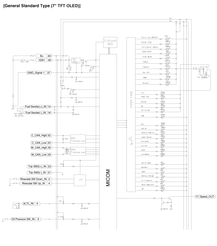
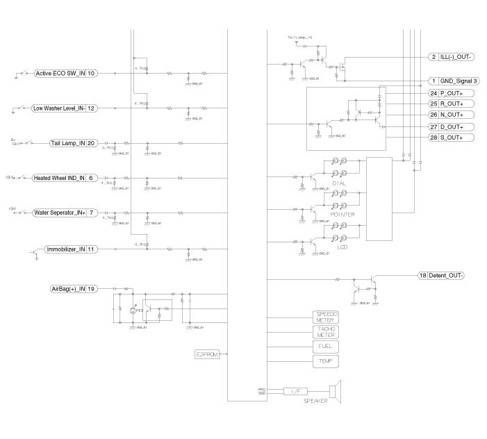
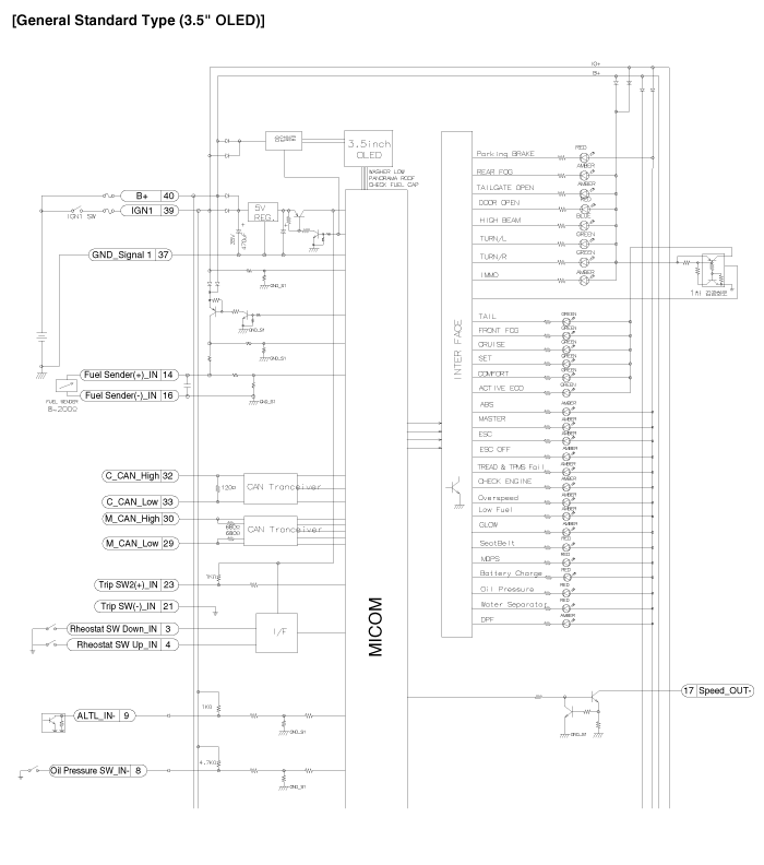
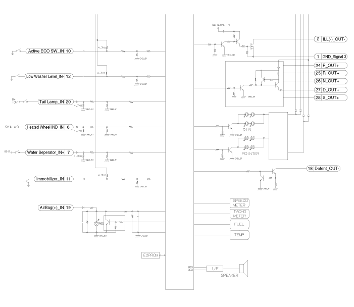
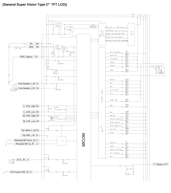
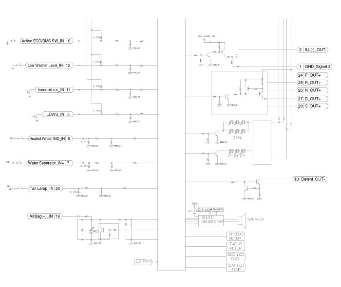
 Instrument Cluster Components and Components Location
Components
Connector Pin Information
No.DescriptionNo.Description1Ground signal321Trip switch1_Input (-) 2Illumination output (-)22-3Rheostat switch (Down)_Input23Trip switch2_Input (-)&nbs ...
 Instrument Cluster Description and Operation
Description
Communication Network Diagram
AbbreviationExplanationACUAirbag Control UnitADMAssist Door ModuleB_CANBody Controller Area NetworkBCMBody Control ModuleBSDBlind Spot DetectionC_CANCha ...
Other Information:
Emergency tailgate safety release
Your vehicle is equipped with an emergency tailgate safety release lever located
on the bottom of the tailgate. When someone is inadvertently locked in the cargo
area, the tailgate can be opened ...
Cluster Ionizer (DATC only) Description and Operation
Description
The cluster ionizer disinfects and decomposes bad smell from
the air conditioner or air inflow. Also, it cleans the inside air of a
vehicle.
When the ignition switch is ON, the ion ...
Categories
- Home
- First Generation
- Second Generation
- Third generation
- Kia Sedona YP 2014-2025 Owners Manual
- Kia Sedona YP 2014-2025 Service Manual
Copyright © www.kisedona.com 2016-2025
