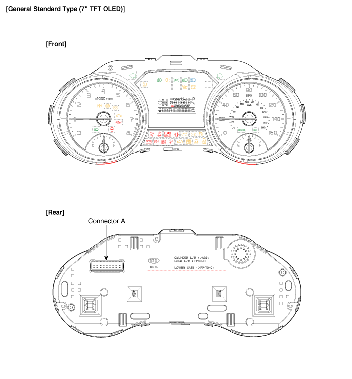
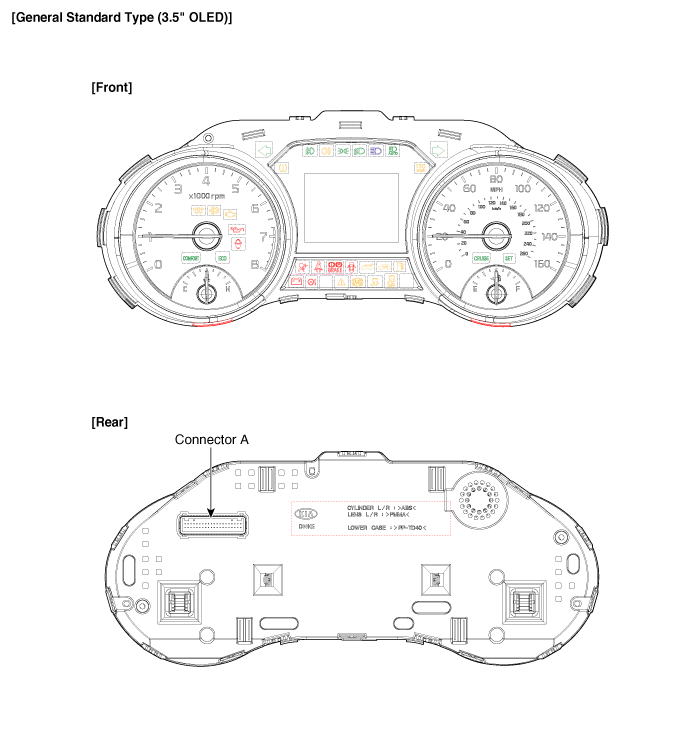
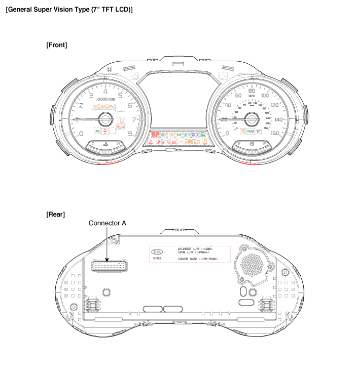
 Kia Sedona: Instrument Cluster Components and Components Location
Third generation YP (2014-2025) / Kia Sedona YP Service Manual / Body Electrical System / Indicators And Gauges / Instrument Cluster Components and Components Location
| Components |


Connector Pin Information
| No. | Description | No. | Description |
| 1 | Ground signal3 | 21 | Trip switch1_Input (-) |
| 2 | Illumination output (-) | 22 | - |
| 3 | Rheostat switch (Down)_Input | 23 | Trip switch2_Input (-) |
| 4 | Rheostat switch (Up)_Input | 24 | AT (''P'' Position) (+) |
| 5 | LDWS_Input | 25 | AT (''R'' Position) (+) |
| 6 | Steering wheel heated indicator_Input | 26 | AT (''N'' Position) (+) |
| 7 | Water seperator_Input (+) | 27 | AT (''D'' Position) (+) |
| 8 | Oil pressure switch_Input (-) | 28 | AT (''S'' Position) (+) |
| 9 | ALTL Input (-) | 29 | Multimedia-CAN (Low) |
| 10 | Active ECO/DMS switch_Input | 30 | Multimedia-CAN (High) |
| 11 | Immobilizer_Input | 31 | - |
| 12 | Low washer level_Input (-) | 32 | Chassis-CAN (High) |
| 13 | - | 33 | Chassis-CAN (Low) |
| 14 | Fuel sender_Input (+) | 34 | - |
| 15 | - | 35 | - |
| 16 | Fuel sender_Input (-) | 36 | - |
| 17 | Speed_Output (-) | 37 | Ground signal1 |
| 18 | Detent_Output (-) | 38 | - |
| 19 | Airbag_Input (+) | 39 | IGN1 |
| 20 | Tail lamp_Input | 40 | Battery (+) |
 Instrument Cluster Schematic Diagrams
Circuit Diagram
...
Other Information:
Oil Filter Body Components and Components Location
Components
1. Oil filter body2. Gasket
...
Repair procedures
Inspection
Tolerance Compensation
Tolerance compensation compensates for the error margins of
surround view video that occur due to the installation tolerance when
the four cameras comprising ...
Categories
- Home
- First Generation
- Second Generation
- Third generation
- Kia Sedona YP 2014-2025 Owners Manual
- Kia Sedona YP 2014-2025 Service Manual
Copyright © www.kisedona.com 2016-2025

