 Kia Sedona: Repair procedures
Third generation YP (2014-2026) / Kia Sedona YP Service Manual / Body Electrical System / BCM (Body Control Module) / Repair procedures
| Removal |
Take care not to scratch the crash pad and related parts. |
| 1. |
Disconnect the negative (-) battery terminal. |
| 2. |
Remove the glove box housing.
(Refer to Body - "Glove Box Housing") |
| 3. |
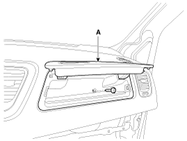
Remove the multi box assembly (A) after loosening the screw.
|
| 4. |
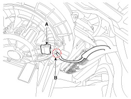
Disconnect the blower motor connector (A) and clip (B).
|
| 5. |
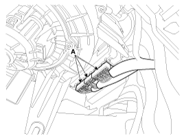
Disconnect the BCM & Receiver unit connectors (A).
|
| 6. |
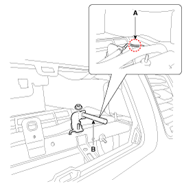
Disconnect the mounting clip (A) and then remove the receiver (B) after loosening the nut.
|
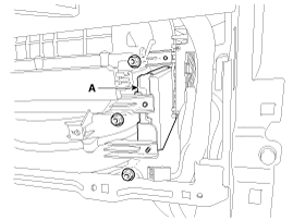
| 7. |
Remove the BCM & Receiver unit (A) after loosening the nuts.
|
| Installation |
| 1. |
Install the BCM & Receiver unit. |
| 2. |
Connect the BCM & Receiver unit connector. |
| 3. |
Connect the blower motor connector. |
| 4. |
Install the multi box assembly. |
| 5. |
Install the glove box housing. |
| 6. |
Connect the negative (-) battery terminal. |
| 7. |
Replace the BCM with a new one and then conduct BCM learning porcedure using GDS. |
| BCM Diagnosis With GDS |
| 1. |
The body electrical system can be quickly diagnosed for faulty parts using vehicle diagnostic system (GDS).
The diagnostic system (GDS) provides the following information:
|
| 2. |
Select the ''Car model'' and the system to be checked in order to check the vehicle with the tester. |
| 3. |
Select the ''Body Control Module (BCM)'' to check body control module. |
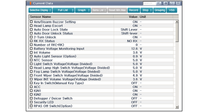
| 4. |
Select the ''Current data" menu to search the current state of the input/output data.
The input/output data for the sensors corresponding to the ''Body Control Module (BCM)'' can be checked.
|
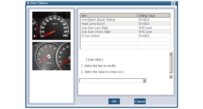
| 5. |
If you want to change user option, select “user option”.
|
 Description and Operation
Description
Communication Network Diagram
Function
FunctionDescriptionInputOutputFRONT WASHER INTER LOCK WIPER- IGN2 On & WasherSW On and Off,- Controlling Wiper Rly depending on Wa ...
Other Information:
SS-B Solenoid Valve(ON/OFF) Repair procedures
Inspection
1.
Turn ignition switch OFF.
2.
Remove the battery and battery tray.
(Refer to Engine Electrical System - "Battery")
3.
Disconnect the solenoid valve connector (A).
4.
Me ...
Crankshaft Position Sensor (CKPS) Repair procedures
Inspection
1.
Check the signal waveform of the CMPS and CKPS using the GDS.
Specification: Refer to “Wave Form”
Removal
1.
Turn the ignition switch OFF and disconnect the battery n ...
Categories
- Home
- First Generation
- Second Generation
- Third generation
- Kia Sedona YP 2014-2026 Owners Manual
- Kia Sedona YP 2014-2026 Service Manual
Copyright © www.kisedona.com 2016-2026


