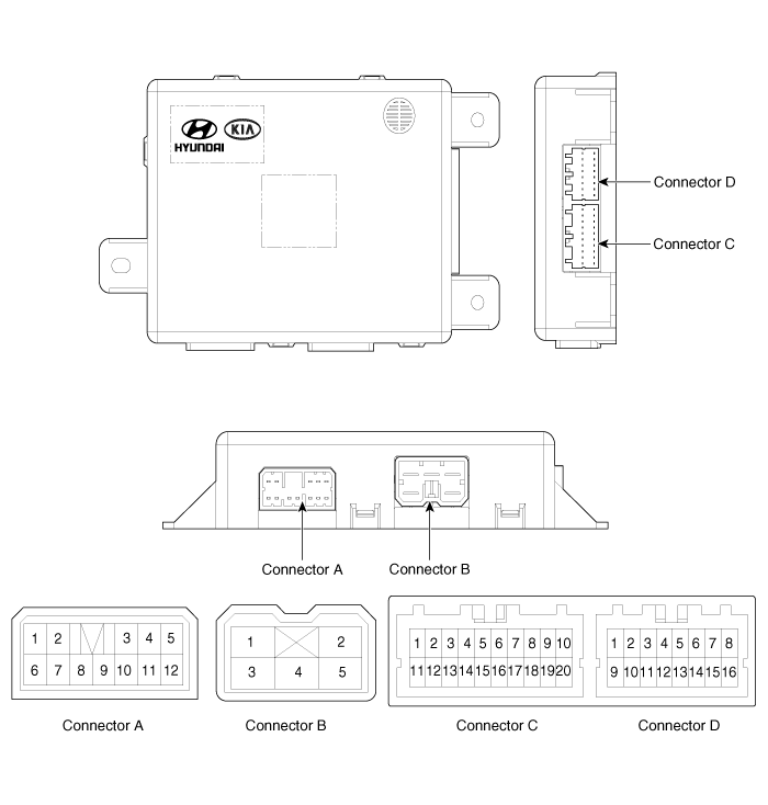
 Kia Sedona: IMS (Integrated Memory System) module Components and Components Location
Third generation YP (2014-2026) / Kia Sedona YP Service Manual / Body Electrical System / IMS (Integrated Memory) / IMS (Integrated Memory System) module Components and Components Location
| Components |

Connector Pin Information
| No. | Connecter A | Connecter B | Connecter C | Connecter D |
| 1 | - | Batt (+) | - | - |
| 2 | Front tilt motor (Up) | GND | - | Seat rear height sensor |
| 3 | Rear height motor (Up) | Batt (+) | Slide switch signal (Forward) | - |
| 4 | Reclining motor (Forward) | - | Reclining switch signal (Forward) | Body CAN (High) |
| 5 | Slide motor (Forward) | GND | Front tilt switch signal (Up) | Body CAN (Low) |
| 6 | - | | Rear height switch signal (Up) | - |
| 7 | Front tilt motor (Down) | Slide sensor | IGN1 | |
| 8 | - | Reclinin sensor | Batt (+) | |
| 9 | - | Front tilt sensor | GND | |
| 10 | Rear height motor (Down) | Seat position sensor power | - | |
| 11 | Reclining motor (Backward) | - | - | |
| 12 | Slide motor (Backward) | - | - | |
| 13 | | Slide switch signal (Backward) | - | |
| 14 | Reclining switch signal (Backward) | - | ||
| 15 | Front tilt switch signal (Down) | - | ||
| 16 | Rear height switch signal (Down) | - | ||
| 17 | - | | ||
| 18 | - | |||
| 19 | - | |||
| 20 | - |
 Description and Operation
Description
This function memorizes the optimized seat position set by
the driver into the power seat unit by operating the IMS switch so that
the personal setting position of the seat can be r ...
 IMS (Integrated Memory System) module Schematic Diagrams
Circuit Diagram
...
Other Information:
KEY OUT indicator
When the ENGINE START/STOP button is in the ACC or ON position, if any door is
open, the system checks for the smart key. If the smart key is not in the vehicle,
the indicator will blink, and if ...
Mode selection
The mode selection button controls the direction of the air flow through the
ventilation system.
The air flow outlet port is converted as follows:
Refer to the illustration in the ...
Categories
- Home
- First Generation
- Second Generation
- Third generation
- Kia Sedona YP 2014-2026 Owners Manual
- Kia Sedona YP 2014-2026 Service Manual
Copyright © www.kisedona.com 2016-2026
