
 Kia Sedona: CVVT Oil Control Valve (OCV) Repair procedures
Third generation YP (2014-2026) / Kia Sedona YP Service Manual / Engine Control / Fuel System / Engine Control System / CVVT Oil Control Valve (OCV) Repair procedures
| Inspection |
| 1. |
Turn the ignition switch OFF. |
| 2. |
Disconnect the OCV connector. |
| 3. |
Measure resistance between the OCV terminals 1 and 2. |
| 4. |
Check that the resistance is within the specification.
|
| Removal |
| [Bank 1/ Intake] |
| 1. |
Turn the ignition switch OFF and disconnect the battery negative (-) terminal. |
| 2. |
Remove the intake manifold.
(Refer to Engine Mechanical System - “Intake Manifold”) |
| 3. |
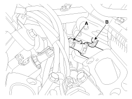
Disconnect the CVVT oil control valve connector (A). |
| 4. |
Remove the installation bolt (B), and then remove the valve from the engine.
|
| [Bank 1/ Exhaust)] |
| 1. |
Turn the ignition switch OFF and disconnect the battery negative (-) terminal. |
| 2. |
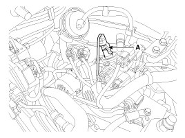
Disconnect the CVVT oil control valve connector (A).
|
| 3. |
Remove the cylinder head cover.
(Refer to Engine Mechanical System - “Cylinder Head Cover”) |
| 4. |
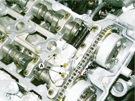
Remove the mounting bolt (A), and then remove the valve from the engine.
|
| [Bank 2/ Intake] |
| 1. |
Turn the ignition switch OFF and disconnect the battery negative (-) terminal. |
| 2. |
Remove the intake manifold.
(Refer to Engine Mechanical System - “Intake Manifold”) |
| 3. |
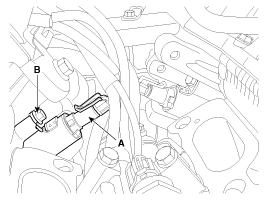
Disconnect the CVVT oil control valve connector (A). |
| 4. |
Remove the installation bolt (B), and then remove the valve from the engine.
|
| [Bank 2/ Exhaust] |
| 1. |
Turn the ignition switch OFF and disconnect the battery negative (-) terminal. |
| 2. |
Disconnect the CVVT oil control valve connector (A).
|
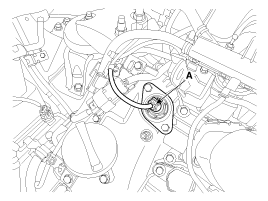
| 3. |
Remove the cylinder head cover.
(Refer to Engine Mechanical System - “Cylinder Head Cover”) |
| 4. |
Remove the mounting bolt (A), and then remove the valve from the engine.
|
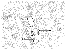
| Installation |
|

|
|
| Items | Component Side | Harness Side |
| Bank 1 (RH) | Grey | |
| Bank 2 (LH) | Black | |
| 1. |
Install in the reverse order of removal.
|
 CVVT Oil Control Valve (OCV) Schematic Diagrams
Circuit Diagram
...
 Variable Intake Solenoid (VIS) Valve Specifications
Specification
ItemSpecificationCoil Resistance (Ω)30.0 ~ 35.0 [20°C(68°F)]
...
Other Information:
Brake Pedal Components and Components Location
Components
1. Cowl bracket2. Brake pedal member assembly3. Brake switch4. Return spring5. Brake pedal stopper6. Clevis pin7. Snap pin8. Brake pedal
...
Owner maintenance schedule
When you stop for fuel:
Check the engine oil level.
Check the coolant level in the coolant reservoir.
Check the windshield washer fluid level.
Look for low or under-inflated tires.
WA ...
Categories
- Home
- First Generation
- Second Generation
- Third generation
- Kia Sedona YP 2014-2026 Owners Manual
- Kia Sedona YP 2014-2026 Service Manual

Copyright © www.kisedona.com 2016-2026