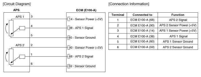
 Kia Sedona: Accelerator Position Sensor (APS) Schematic Diagrams
Third generation YP (2014-2026) / Kia Sedona YP Service Manual / Engine Control / Fuel System / Engine Control System / Accelerator Position Sensor (APS) Schematic Diagrams
| Circuit Diagram |

 Accelerator Position Sensor (APS) Description and Operation
Description
Accelerator Position Sensor (APS), installed on the
accelerator pedal module, detects the rotation angle of the accelerator
pedal. The APS, one of the most important sensors in engi ...
 Accelerator Position Sensor (APS) Repair procedures
Inspection
1.
Connect the GDS on the Data Link Connector (DLC).
2.
Turn the ignition switch ON.
3.
Measure the output voltage of the APS 1 and 2 at C.T and W.O.T.
AcceleratorPositionOut ...
Other Information:
CVVT (Continuous Variable Valve Timing) System Description and Operation
Description
Continuous Variable Valve Timing (CVVT) system advances or
retards the valve timing of the intake and exhaust valve in accordance
with the ECM control signal which is calculated by ...
Smart Cruise Control Unit Schematic Diagrams
Circuit Diagram
...
Categories
- Home
- First Generation
- Second Generation
- Third generation
- Kia Sedona YP 2014-2026 Owners Manual
- Kia Sedona YP 2014-2026 Service Manual
Copyright © www.kisedona.com 2016-2026
