 Kia Sedona: Rail Pressure Sensor (RPS) Repair procedures
Third generation YP (2014-2026) / Kia Sedona YP Service Manual / Engine Control / Fuel System / Engine Control System / Rail Pressure Sensor (RPS) Repair procedures
| Inspection |
| 1. |
Connect the GDS to the Data Link Connector (DLC). |
| 2. |
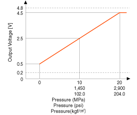
Measure the output voltage of the RPS at idle and various engine speed.
|
| Removal |
| 1. |
Turn the ignition switch OFF and disconnect the battery negative (-) terminal. |
| 2. |
Release the residual pressure in fuel line.
(Refer to the Fuel Delivery System - Repair Procedures - "Release Residual Pressure in Fuel Line"). |
| 3. |
Remove the intake manifold.
(Refer to Engine Mechanical System - “Intake Manifold”) |
| 4. |
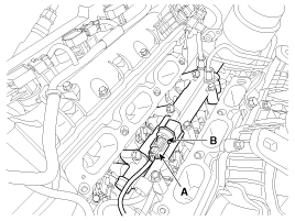
Disconnect the rail pressure sensor connector (A), and then remove the sensor (B) from the delivery pipe.
|
| Installation |
|
| 1. |
Install in the reverse order of removal.
|
 Rail Pressure Sensor (RPS) Schematic Diagrams
Circuit Diagram
...
 Rail Pressure Sensor (RPS) Troubleshooting
Signal Waveform
...
Other Information:
Power Seat Control Switch Repair procedures
Inspection
Diagnosis With GDS
1.
The body electrical system can be quickly diagnosed for faulty parts using vehicle diagnostic system (GDS).
The diagnostic system (GDS) provides the following in ...
Rear Shock Absorber Repair procedures
Removal
1.
Remove the rear wheel and tire (A) from rear hub.
Tightening torque:
88.2 ~ 107.8 N.m (9.0 ~ 11.0 kgf.m, 65.0 ~ 79.5 lb-ft)
Be careful not to damage ...
Categories
- Home
- First Generation
- Second Generation
- Third generation
- Kia Sedona YP 2014-2026 Owners Manual
- Kia Sedona YP 2014-2026 Service Manual
Copyright © www.kisedona.com 2016-2026


