 Kia Sedona: Specifications
Third generation YP (2014-2026) / Kia Sedona YP Service Manual / Engine Electrical System / Specifications
| Specification |
| Ignition System |
Ignition Coil
| Item | Specification |
| Rated Voltage (V) | 12 |
| Operating Voltage (V) | 5 ~ 16 |
| Primary Coil Resistance (Ω) | 0.62 ± 10% [20°C (68°F)] |
| Secondary Coil Resistance (kΩ) | 7.0 ± 15% [20°C (68°F)] |
Spark plug
| Item | Specification |
| Type | SILZKR7B11 |
| Gap | 1.0 ~ 1.1 mm (0.0394 ~ 0.0433 in.) |
| Insulation resistance (MΩ) | 10 or more |
Condenser
| Item | Specification |
| Capacitance (uF) | 0.47 [1KHz] |
| Insulation resistance (MΩ) | 1,000 [DC 500 V/1 Min] |
| Charging System |
Alternator
| Item | Specification |
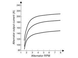
| Rated voltage | 13.5V , 150A |
| Speed in use | 1,500 ~ 18,000rpm |
| Voltage regulator | IC Regulator built in type |
| Default regulated voltage (V) [COM terminal] | 14.0 ~ 15.5 (-35°C) |
| 14.0 ~ 15.0 (25°C) | |
| 13.1 ~ 15.0 (140°C) | |
| Regulator Setting Voltage (V) [COM terminal] | 11.6 ~ 15.4 [5,000 rpm / min / 10A] |

Battery
| Item | Specification |
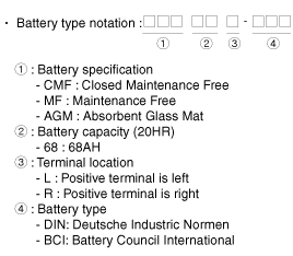
| Model type | CMF80L-BCI |
| Capacity [20HR/5HR] (AH) | 80/64 |
| Cold Cranking Amperage (A) | 660 (SAE) / 528 (EN) |
| Reserve Capacity (Min) | 145 |
|
| Starting System |
Starter
| Item | Specification | |
| Rated voltage | 12 V, 1.7 kW | |
| The number of pinion teeth | 12 | |
| Performance [No-load, 11.5 V] | Ampere | Max. 85 A |
| Speed | Min. 2,550 rpm | |
| Tightening Torques |
| Item | N.m | kgf.m | lb-ft |
| Ignition coil mounting bolt | 9.8 ~ 11.8 | 1.0 ~ 1.2 | 7.2 ~ 8.7 |
| Spark plug | 14.7 ~ 24.5 | 1.5 ~ 2.5 | 10.9 ~ 18.1 |
| Condenser & Flange bracket mounting bolt | 9.8 ~ 11.8 | 1.0 ~ 1.2 | 7.2 ~ 8.7 |
| Alternator mounting bolt | 49.0 ~ 63.7 | 5.0 ~ 6.5 | 36.2 ~ 47.0 |
| Battery (+) terminal tightening nut | 7.8 ~ 9.8 | 0.8 ~ 1.0 | 5.2 ~ 8.7 |
| Battery (-) terminal tightening nut | 4.0 ~ 6.0 | 0.4 ~ 0.6 | 2.9 ~ 4.3 |
| Battery bracket mounting bolt | 8.8 ~ 13.7 | 0.9 ~ 1.4 | 6.5 ~ 10.1 |
| Battery tray mounting bolt | 8.8 ~ 13.7 | 0.9 ~1.4 | 6.5 ~ 10.1 |
| Battery sensor cable flange mounting bolt (Chassis ground) | 21.6 ~ 32.4 | 2.2 ~ 3.3 | 16.0 ~ 23.9 |
| Starter mounting bolt | 49.0 ~ 63.7 | 5.0 ~ 6.5 | 36.2 ~ 47.0 |
| Starter cover mounting bolt | 8.8 ~ 13.7 | 0.9 ~ 1.4 | 6.5 ~ 10.1 |
 Special Service Tools
Special Service Tools
Tool Name / NumberIllustrationDescription09964-C1100SCC reflectorReflector to align the SCC radar09964-C1200Vertical / horizontal laserLaser to detect the center of the vehi ...
Other Information:
Schematic Diagrams
Schematic Diagram
Canister
Canister is filled with charcoal and absorbs evaporated vapor
in fuel tank. The gathered fuel vapor in canister is drawn into the
intake manifold by the ECM/PCM when ...
Transmitter precautions
The transmitter will not work if any of following occur :
- The ignition key is in the ignition switch.
- You exceed the operating distance limit (about 10 m [30 feet]).
- The battery in the t ...
Categories
- Home
- First Generation
- Second Generation
- Third generation
- Kia Sedona YP 2014-2026 Owners Manual
- Kia Sedona YP 2014-2026 Service Manual
Copyright © www.kisedona.com 2016-2026


