 Kia Sedona: Variable Intake Solenoid(VIS) Actuator Repair procedures
Third generation YP (2014-2025) / Kia Sedona YP Service Manual / Engine Mechanical System / Intake And Exhaust System / Variable Intake Solenoid(VIS) Actuator Repair procedures
| Removal and Installation |
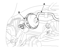
VIS 1 [Intake Manifold]
| 1. |
Disconnect the battery "-" terminal. |
| 2. |
Remove the engine cover.
(Refer to Engine and Transaxle Assembly - "Engine Cover") |
| 3. |
Disconnect the VIS actuator hose (A). |
| 4. |
Remove the VIS actuator (B).
|
| 5. |
Install in the reverse order of removal. |
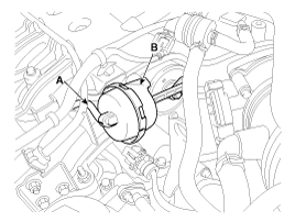
VIS 2 [Surge Tank]
| 1. |
Disconnect the battery "-" terminal. |
| 2. |
Remove the engine cover.
(Refer to Engine and Transaxle Assembly - "Engine Cover") |
| 3. |
Disconnect the VIS actuator hose (A). |
| 4. |
Remove the VIS actuator (B).
|
| 5. |
Install in the reverse order of removal. |
 Exhaust Manifold Repair procedures
Removal and Installation
[LH Exhaust Manifold]
1.
Disconnect the battery negative terminal.
2.
Remove the engine cover.
(Refer to Engine and Transaxle Assembly - "Engine Cover")
3.
Remov ...
 Muffler Components and Components Location
Components
1. Gasket2. Hanger3. Front muffler4. Catalytic converter & Center muffler assembly5. Rear muffler6. Tail muffler
...
Other Information:
Smart Tailgate Unit Components and Components Location
Components
...
Auto Light Sensor Repair procedures
Inspection
Check if the auto light control operates like a timing chart
shown below. Tail lamp output and head lamp (Low) output is controlled
based on the auto light sensor''s input (illuminat ...
Categories
- Home
- First Generation
- Second Generation
- Third generation
- Kia Sedona YP 2014-2025 Owners Manual
- Kia Sedona YP 2014-2025 Service Manual
Copyright В© www.kisedona.com 2016-2025


