 Kia Sedona: Repair procedures
Third generation YP (2014-2026) / Kia Sedona YP Service Manual / Body Electrical System / Surround View Monitoring (SVM) System / Repair procedures
| Inspection |
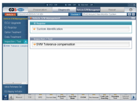
Tolerance Compensation
Tolerance compensation compensates for the error margins of
surround view video that occur due to the installation tolerance when
the four cameras comprising the SVM system are installed.
Tolerance compensation must be carried out when the following actions are performed:
| – |
When removing and installing a wide camera. |
| – |
When conducting a body task such as the trunk task that causes the focus of the wide camera to change. |
| – |
When replacing the door mirror with a wide camera. |
| – |
When replacing the surround view monitoring unit. |
Tolerance Compensation Environments
There are two types of tolerance compensations: [manual tolerance compensation] and [automatic tolerance compensation].
The service center with the SVM exclusive workshop performs [automatic tolerance compensation].
The maintenance environment without the SVM exclusive workshop performs [manual tolerance compensation]. |

The Procedure of Manual Tolerance Compensation
| 1. |
Advanced preparations will be made according to the following.
|
| 2. |
The following processes will be performed to confirm whether
or not the SVM ECU and camera are working properly before engaging
tolerance compensation mode.
|
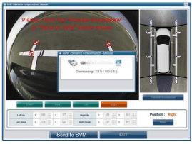
| 3. |
To perform SVM manual footage compensation the equipment in the figure below must be interconnected with the vehicle.
|
| 4. |
The vehicle''s ignition (IG) must be turned off. |
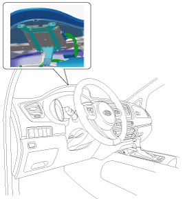
| 5. |
Remove the Instrument Cluster to connect the connector of the GDS-SVM device to the vehicle''s SVM module.
(Refer to Surround View Monitoring (SVM) System - "Surround View Monitoring Unit") |
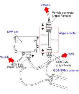
| 6. |
The wire harness and connecting connector (24 pins) running from the SVM unit to the vehicle side will be removed.
|
| 7. |
The GDS-SVM Image Capture equipment connector (24-pin) will be connected to the same location as the SVM unit connector.
|

| 8. |
The GDS VCI and vehicle are connected by DLC cable.
|
| 9. |
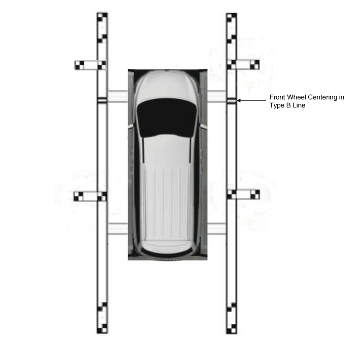
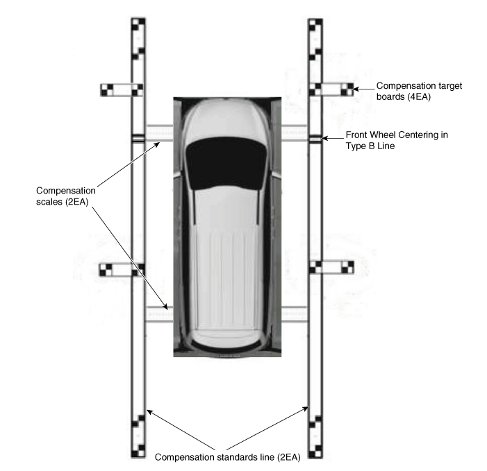
Install around the vehicle by referring to the guide that was
provided along with the compensation scales (2), compensation standard
line boards (2), and compensation target boards (4).
|
| 10. |
Keep the IG on while the car is stopped, confirm the gear selecter is in Park ''P'' and engage the parking brake on a flat area. |
| 11. |
Perform the work with the SVM switch in the vehicle set to ‘ON.’ |
| 12. |
Perform SVM manual tolerance compensation according to GDS diagnostics display.
|
| 13. |
The next procedure is to proceed by referring to the GDS
screen instructions and the ‘manual tolerance compensation’ manual
supplied along with the equipment.
|
 Schematic Diagrams
SVM System Input/Output
1.
Camera input
ItemSpecificationLens angle of view190 degreesAngle of viewHorizontal186 degreesVertical135 degreesFunctionProvides the original image of the wide ang ...

Other Information:
To resume cruise control set speed
If any method other than the CRUISE button was used to cancel cruising speed
and the system is still activated, the cruising speed will automatically resume
when you move the lever up/down (to R ...
Rear Seat Belt Buckle Repair procedures
Replacement
[Second row seat belt buckle]
1.
Using a screwdriver or remover, remove the leg outer cover (A).
2.
Remove the second row seat belt buckle (A) after loosening the bolt.
3.
I ...
Categories
- Home
- First Generation
- Second Generation
- Third generation
- Kia Sedona YP 2014-2026 Owners Manual
- Kia Sedona YP 2014-2026 Service Manual

Copyright © www.kisedona.com 2016-2026