 Kia Sedona: Schematic Diagrams
Third generation YP (2014-2026) / Kia Sedona YP Service Manual / Body Electrical System / Sun Roof / Schematic Diagrams
| Circuit Diagram |
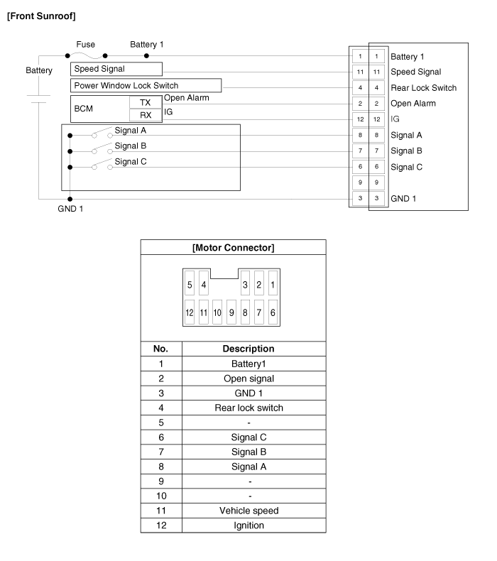
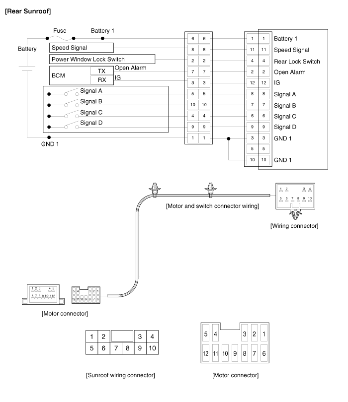
Connector Pin Information
| No. | Motor Connector | Sunroof Wiring Connector |
| 1 | Battery 1 | GND 1 |
| 2 | Open alarm | Rear lock switch |
| 3 | GND 1 | IGN |
| 4 | Rear lock switch | Signal C |
| 5 | - | Signal A |
| 6 | Signal C | Battery 1 |
| 7 | Signal B | Open alarm |
| 8 | Signal A | Speed signal |
| 9 | Signal D | Signal D |
| 10 | GND 1 | Signal B |
| 11 | Speed signal | |
| 12 | IGN |
 Components and Components Location
Component Location
1. Front sunroof2. Front & Rear sunroof switch3. Front sunroof motor & controller4. Rear sunroof5. Rear sunroof switch6. Rear sunroof motor & Controller
...
 Sunroof Switch Components and Components Location
Components
...
Other Information:
Finish maintenance
Washing
To help protect your vehicle ...
Closing the hood
1. Before closing the hood, check the following:
All filler caps in the engine compartment must be correctly installed.
Gloves, rags or any other combustible material must be removed from the
...
Categories
- Home
- First Generation
- Second Generation
- Third generation
- Kia Sedona YP 2014-2026 Owners Manual
- Kia Sedona YP 2014-2026 Service Manual

Copyright © www.kisedona.com 2016-2026