 Kia Sedona: Description and Operation
Third generation YP (2014-2026) / Kia Sedona YP Service Manual / Body Electrical System / Lane Departure Warning System (LDWS) / Description and Operation
| Description |
Block Diagram
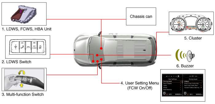
LDWS is composed of below units
| No | Item | Function | Position | ||||||
| 1 | LDWS UNIT |
| Windshield Glass | ||||||
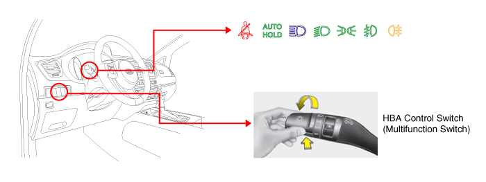
| 2 | LDWS Switch | LDWS On/Off Switch | Crash Pad (Left) | ||||||
| 3 | Multi-function Switch | HBA On/Off Switch (MF : Auto mode) | Steering Wheel | ||||||
| 4 | User Setting Menu | FCW On/Off Menu | Cluster menu | ||||||
| 5 | Cluster/Buzzer | FCW/LDWS Waning | Cluster |
Camera unit of the LDWS processes the following functions using the video signal input.
| – |
Detect and analyze drive lane |
| – |
Detect the light from foregoing vehicle |
| – |
Detect and analyze status of foregoing vehicle, and make warning sounds (or message) for driver if necessary |
| – |
Transmits the information using high speed CAN communication |
| 1. |
Lane Departure Warning System (LDWS) unit
The lane departure warning system is a convenient device that
recognizes the lanes ahead using the camera image and vehicle signal
informtaion and alarms the driver in case of deviation from the lane. It
consists of the camera unit and recognizes the lane by calculating the
camera image input signal.
The sensor module for screen image processing by sensing the
lane ahead on the camera unit senses the lane to keep the lane and
calculates the key parameters, i.e. vehicle center offset, road width,
vehicle driving angle and road curvature. The following procedures are
the lane recognizing process through screen image processing.
|
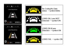
| 2. |
LDWS Operation process
When the LDWS switch is pressed, the operation state of the
lane departure warning system is displayed at the center while the LDWS
lamp is on.
The specific classification of the displays is shown in the following table.
| ||||||||||||||||||||
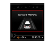
| 3. |
FCWS Operation process
| ||||||||||||||||||||||||
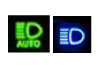
| 4. |
High Beam Assist
(Multi-function Switch Auto/High beam position)
| ||||||||||||||||||||

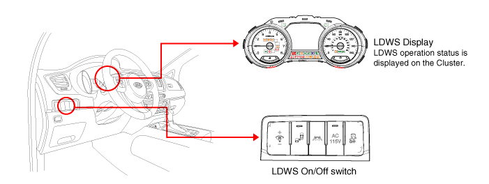
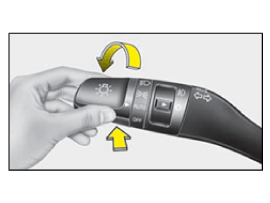
LDWS ON/OFF switch (A)
When the LDWS switch is pressed, the LDWS is on while the
LDWS lamp is on. When the switch is pressed again, the LDWS is off and
the display lamp is off.
High Beam Auto Control Switch: High Beam Auto Control System
is turned ON if the Multifunction Switch Light SW is set to AUTO, and
the Light SW is set to High Beam position (Pushed).
| – |
If the Light SW is not set to AUTO, or to High Beam position, the High Beam Auto Control System is turned OFF. |
The alarm method of LDWS
| 1. |
Visual alarm : The lane to the direction of departure is blinked in yellow. |
The operating conditions of LDWS
The operating conditions of LDWS is as below.
| 1. |
The switch for LDWS shall be ON. The LDWS lamp is on in the instrument panel when the switch is on. |
| 2. |
It operates when the LDWS function is set beyond 70km/h (44mph) of vehicle speed.
The alarming function is stopped tentatively when the vehicle
speed is lower than 65~70km/h (41~44mph) and the alarming is restarted
when it is over 70km/h (44mph). |
| 3. |
If the driver operates left and right turning lamps to inform
the intention of lane change, there will be no alarm regardless of the
direction of lane departure.
The lane departure alarming function is restarted after 2 seconds from switching off the left and right turning lamps.
There will be no alarm when operating the hazard lamps. |
| 4. |
Operate the switch for turning lamps and then change the
lane. Random changing of lanes without operating the turning lamps to
the driving direction generates the alarm. |
| 5. |
When more than 40% of the vehicle body has crossed the lane, the alarm is released by sensing departure for lane change. |
| 6. |
The lane departure alarming is not made when the vehicle drives at the center of the lane.
|


 Components and Components Location
Components
1. LDWS ON/OFF switch2. Instrument cluster3. LDWS unit
...
 Repair procedures
Service Point Target Auto Calibration (SPTAC)
This procedure provides a way to calibrate the camera by
having the service technician align the car to a well lit simulated
straight road target; ...
Other Information:
Rear climate control
To turn on the rear climate control system;
From the front seat
1. Set the rear climate control selection (REAR ON) button in the front climate
control panel to the ON position.
2. Set the rear f ...
Components and Components Location
Component Location
1. Drive power window switch2. Passenger power window switch3. Front window motor4. Rear window motor5. Rear window switch
...
Categories
- Home
- First Generation
- Second Generation
- Third generation
- Kia Sedona YP 2014-2026 Owners Manual
- Kia Sedona YP 2014-2026 Service Manual

Copyright © www.kisedona.com 2016-2026