 Kia Sedona: MTS Control Unit Repair procedures
Third generation YP (2014-2026) / Kia Sedona YP Service Manual / Body Electrical System / MTS System / MTS Control Unit Repair procedures
| Removal |
[AVN Type]
|
| 1. |
Disconnect the negative (-) battery terminal. |
| 2. |
Remove the center fascia upper panel.
(Refer to Body - "Center Fascia Panel") |
| 3. |
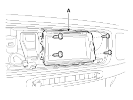
Remove the AVN head unit (A) after loosening the screws.
|
| 4. |
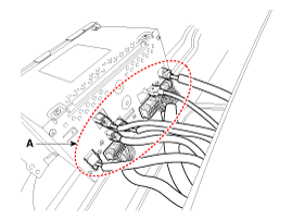
Disconnet the AVN head unit connectors (A).
|
[UVO AUDIO + MTS Type]
| 1. |
Disconnect the negative (-) battery terminal. |
| 2. |
Remove the cluster.
(Refer to Indicators And Gauges - "Instrument Cluster") |
| 3. |
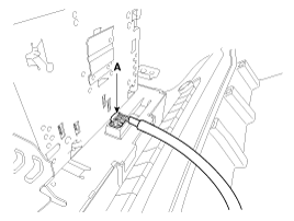
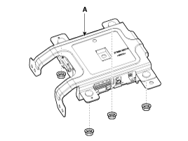
Disconnect the MTS unit connectors (A).
|
| 4. |
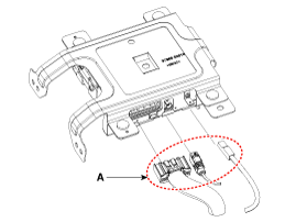
Remove the MTS unit (A) after loosening the nuts.
|
| Installation |
[AVN Type]
| 1. |
Connect the AVN head unit connector. |
| 2. |
Install the AVN head unit. |
| 3. |
Install the center fascia upper panel. |
| 4. |
Connect the negative (-) battery terminal.
|
[UVO AUDIO + MTS Type]
| 1. |
Install the MTS unit. |
| 2. |
Connect the MTS unit connector. |
| 3. |
Install the cluster. |
| 4. |
Connect the negative (-) battery terminal. |
| Inspection |
| Diagnosis With GDS |
| 1. |
The body electrical system can be quickly diagnosed for
faulty parts using vehicle diagnostic system (GDS). The diagnostic
system (GDS) provides the following information:
|
| 2. |
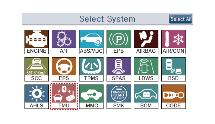
Select the ''Car model'' and the system to be checked in order to check the vehicle with the tester. |
| 3. |
Select the ''Telematics Unit (TMU)'' to check the telematics unit. |
| 4. |
Select the ''Current Data" menu to search the current state of the input/output data.
The input/output data for the sensors corresponding to the TMU can be checked.
|
| 5. |
To check the DTC of the TMU, select "Diagnostic trouble codes". |
 MTS Control Unit Components and Components Location
Component (Only for the audio TMU System)
The UVO unit for AVN is integrated in the AVN head unit. ...
Other Information:
Ignition Coil Repair procedures
Removal
Ignition coil (Cylinder #1) [Bank 1]
1.
Remove the surge tank.
(Refer to Engine Mechanical System - "Surge Tank")
2.
Disconnect the Ignition coil connector (A).
3.
Remove the i ...
Transaxle Control Module (TCM) Repair procedures
Inspection
1.
TCM ground circuit test: Measure resistance between TCM and
chassis ground using the backside of TCM harness connector as TCM side check point.
Specification: Below 1Ω
...
Categories
- Home
- First Generation
- Second Generation
- Third generation
- Kia Sedona YP 2014-2026 Owners Manual
- Kia Sedona YP 2014-2026 Service Manual
Copyright © www.kisedona.com 2016-2026


