 Kia Sedona: Massage Control Unit Repair procedures
Third generation YP (2014-2026) / Kia Sedona YP Service Manual / Body Electrical System / Seat Electrical / Massage Control Unit Repair procedures
| Removal |
| 1. |
Disconnect the negative (-) battery terminal. |
| 2. |
Remove the front seat back cover.
(Refer to Body - "Front Seat Back Cover") |
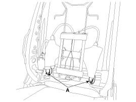
| 3. |
Disconnect the lumbar support motor connectors (A).
|
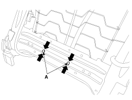
| 4. |
Press the 2 mounting clips (A) from front seat back.
|
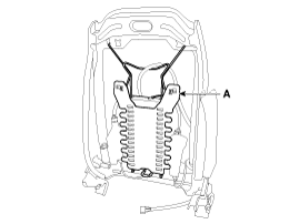
| 5. |
Remove the lumber support assembly (A).
|
| Installation |
| 1. |
Install the lumbar support assembly. |
| 2. |
Connect the lumbar support motor connectors. |
| 3. |
Install the front seat back cover. |
| 4. |
Connect the negative (-) battery terminal. |
| Inspection |
Diagnosis With GDS
| 1. |
The body electrical system can be quickly diagnosed for faulty parts using vehicle diagnostic system (GDS).
The diagnostic system (GDS) provides the following information:
|
| 2. |
Select the ''Car model'' and the system to be checked in order to check the vehicle with the tester. |
| 3. |
Select the ''Power seat module (PSM)'' to check the power seat module (PSM). |
| 4. |
Select the ''Current Data" menu to search the current state of the input/output data.
The input/output data for the sensors corresponding to the power seat module (PSM) can be checked. |
| 5. |
If you wish to check the power door lock operation by force, select "Actuation test". |
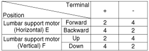
Lumbar Support Motor
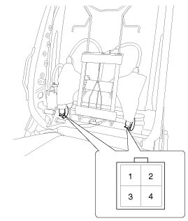
| 1. |
Disconnect the connectors for each motor.
[Lumbar support motor]
|
| 2. |
With the battery connected directly to the motor terminals, check if the motors run smoothly. |
| 3. |
Reverse the connections and check that the motor turns in reverse. |
| 4. |
If there is an abnormality, replace the motors.
|
 Massage Control Unit Components and Components Location
Components
Mechanical Lumbar Support Assembly
[4 Way Lumbar]
[2 Way Lumbar]
...
 Smart key System
...
Other Information:
Description and Operation
Description
It''s a system that uses illumination sensor to automatically
turn ON the tail lamp and head lamp based on the change in surrounding
environment''s illumination condition. It activa ...
Do not install a child restraint on the front passenger
Never place a rear-facing child restraint in the front passenger ...
Categories
- Home
- First Generation
- Second Generation
- Third generation
- Kia Sedona YP 2014-2026 Owners Manual
- Kia Sedona YP 2014-2026 Service Manual

Copyright © www.kisedona.com 2016-2026