 Kia Sedona: Heated Oxygen Sensor (HO2S) Repair procedures
Third generation YP (2014-2025) / Kia Sedona YP Service Manual / Engine Control / Fuel System / Engine Control System / Heated Oxygen Sensor (HO2S) Repair procedures
| Inspection |
| 1. |
Turn the ignition switch OFF. |
| 2. |
Disconnect the HO2S connector. |
| 3. |
Measure resistance between the HO2S terminals 3 and 4. |
| 4. |
Check that the resistance is within the specification.
|
| Removal |
Note that the SST (Part No : 09392-1Y100 or 09392-2H100) is used when removing the heated oxygen sensor. |
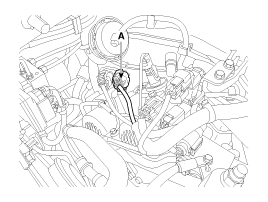
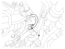
| [Bank 1/Sensor 1] |
| 1. |
Turn the ignition switch OFF and disconnect the battery negative (-) terminal. |
| 2. |
Disconnect the connector (A).
|
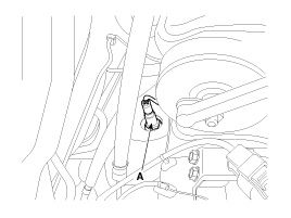
| 3. |
Remove the heated oxygen sensor (A).
|
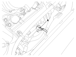
| [Bank 1/Sensor 2] |
| 1. |
Turn the ignition switch OFF and disconnect the battery negative (-) terminal. |
| 2. |
Disconnect the connector (A).
|
| 3. |
Remove the heated oxygen sensor (A).
|
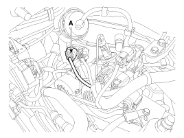
| [Bank 2/Sensor 1] |
| 1. |
Turn the ignition switch OFF and disconnect the battery negative (-) terminal. |
| 2. |
Disconnect the connector (A).
|
| 3. |
Remove the heated oxygen sensor (A).
|
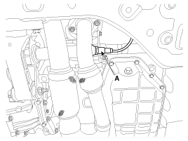
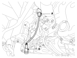
| [Bank 2/Sensor 2] |
| 1. |
Turn the ignition switch OFF and disconnect the battery negative (-) terminal. |
| 2. |
Disconnect the connector (A). |
| 3. |
Remove the heated oxygen sensor (B).
|
| Installation |
|
Note that the SST (Part No : 09392-1Y100 or 09392-2H100) is used when removing the heated oxygen sensor. |
| 1. |
Install in the reverse order of removal.
|
 Heated Oxygen Sensor (HO2S) Schematic Diagrams
Circuit Diagram
...
 Heated Oxygen Sensor (HO2S) Troubleshooting
Wave Form
...
Other Information:
Front Seat Shield Inner Cover Components and Components Location
Component Location
1. Front seat shield inner cover
...
Schematic Diagrams
Circuit Diagram
1.
Connector terminal
TypePin NoDescriptionBattery1Battery -2Battery +Vehicle1-2-3-4-5-6-7IGN8High_CAN9Low_CAN10-11-12-
2.
Circuit Diagram ...
Categories
- Home
- First Generation
- Second Generation
- Third generation
- Kia Sedona YP 2014-2025 Owners Manual
- Kia Sedona YP 2014-2025 Service Manual
Copyright © www.kisedona.com 2016-2025


