 Kia Sedona: Hazard Lamp Switch Repair procedures
Third generation YP (2014-2026) / Kia Sedona YP Service Manual / Body Electrical System / Lighting System / Hazard Lamp Switch Repair procedures
| Inspection |
| 1. |
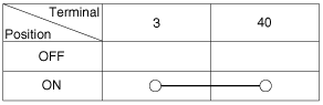
Check for continuity between terminals. If the continuity is not as specified, replace the hazard lamp switch.
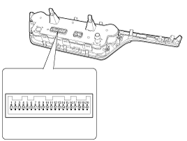
Connector Pin Information
|
| Removal |
| 1. |
Disconnect the negative (-) battery terminal. |
| 2. |
Remove the center fascia lower panel.
(Refer to Body - "Center Fascia Panel") |
| 3. |
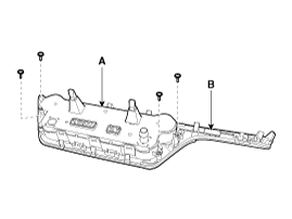
Remove the heater & A/C control unit (A) after loosening the screws from the center fascia lower panel (B).
|
| Installation |
| 1. |
Install the heater & A/C control unit. |
| 2. |
Install the center fascia lower panel. |
| 3. |
Connect the negative (-) battery terminal. |
 Overhead Console Lamp Repair procedures
Removal
1.
Disconnect the negative (-) battery terminal.
2.
Remove the overhead console lamp (A) after loosening the screws.
3.
Disconnect the connector (A) from the overhead console lamp. ...
 Rheostat Components and Components Location
Components
...
Other Information:
Input Speed Sensor Description and Operation
Description
•
Input speed sensor uses an electric current type hall sensor in which the current is changed by the magnetic variation.
•
Input speed sensor (A) and output speed ...
228,000 km (142,500 miles) or 114 months
❑ Rotate tire
❑ Inspect battery condition
❑ Inspect air cleaner filter
❑ Inspect vacuum hose
❑ Inspect power steering fluid (if equipped)
❑ Inspect power ...
Categories
- Home
- First Generation
- Second Generation
- Third generation
- Kia Sedona YP 2014-2026 Owners Manual
- Kia Sedona YP 2014-2026 Service Manual

Copyright © www.kisedona.com 2016-2026